
Hardware components | ||||||
 |
| × | 1 | |||
 |
| × | 1 | |||
 |
| × | 1 | |||
Software apps and online services | ||||||
 |
| |||||
| ||||||
| ||||||
Hand tools and fabrication machines | ||||||
 |
| |||||
 |
| |||||
Data analysis is a key issue in Science, Technology, Engineering, and Mathematics (STEM). The ability to visualise data is crucial to make sense of it and draw conclusions. Therefore, students who are visually impaired are at a disadvantage and can be discouraged to pursue a career in science. Many tools have been developed to overcome this challenge, however, they often rely on verbal descriptions or static tactile pictures, which can be limiting. It has been reported that a combination of tactile and auditory stimuli can improve blind students' learning of visual topics such as geometry [1]. It is clear the need to make STEM subjects more accessible to the visually impaired, therefore in this project, we aim to build an inexpensive 3D tracker for dynamic auditive data representation.
PlanThe idea is to build a device that translates mathematical functions (on the real line, plane or 3D space) into sound. We can navigate the space by detecting the position of the user's hand with a 3D-tracking sensor such as the Flick or the Skywriter, which uses the MGC3130 chip. The recorded position can then be used as input for a mathematical function whose output can be processed into a sound signal. The data acquisition can be easily done by connecting the 3D-tracker to an Arduino or RaspberryPi, we can then process the data and send the output to a sound processing software such as Supercollider or CSound.
As we intend this to be an inclusive technology we will also attempt to include visual and tactile feedback. For visualising the data, we can use Processing, which is a simple programing language specifically developed for visual artists. The tactile feedback can be achieved by different means. On one hand, we can use ultrasonic transducers to create haptic feedback in mid-air (Ultraino). On the other hand, we could use vibration motors to emulate different textures (Hap2U).
At the moment we are still not sure which is the best way to include tactile feedback, but we will keep updating.
Arduino, Processing, and Supercollider for ChromebooksThe necessary software for our project is available for Windows, Mac, and Linux systems, but not for Chrome OS. In case you are using a Chromebook, there are some options to work around it. The first one is to use web editors for Arduino and Processing, unfortunately, there is not an online option for Supercollider. An alternative is the CSound web IDE but we find Supercollider easier to work with. The second option is to install Linux, which can be done in several ways. The simplest one is to enable the native Chrome OS Linux (beta) virtual machine and install the Linux apps. The problem with this method is that the virtual machine still has some issues, in particular setting up the audio is not so easy and using Supercollider is virtually impossible. Another way to install Linux on a Chromebook is to use Crouton, which gives us a Linux distribution in which sound can be configured more easily. There is still an extra step to get the Supercollider server to run, forwarding JACK to CRAS. Beware that this method requires enabling the developer's mode which voids your Chromebook warranty.
Arduino basics- Code structure
- Variables
- Functions
Client-server architecture
- Evaluating lines
- Variables
- Fundamental oscillators
- Synths
- Code structure
- Variables
- Functions
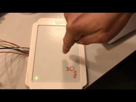
The first step is to obtain the position data. We use the Flick Large from Pi Supply, but the Skywriter from Pimoroni can be connected the same way, and actually, both use the same Arduino library. The Flick has 8 male pins, two for power (VCC, GND) two for data communication (SDA, SCL), and four digital pins (TS, RESET, LED1, LED2). The first four have to be connected to the corresponding pins in the Elegoo (Arduino) UNO R3, the other four can be connected to any digital pins in the Elegoo. Below we show the schematic connection, the Skywriter should be connected similarly, except for the LED pins which are not present in this case.
To control the Flick we use the Skywriter library by Pimoroni. After downloading it we install the library by copying the Skywriter directory into the Arduino libraries directory. We can now launch the Arduino IDE and begin coding. A simple example is to track position and display it on the serial monitor. To enable communication on the serial port we include the next two libraries
#include <Wire.h>
#include <skywriter.h>
Then we initialize the Arduino board as follows
void setup() {
  Serial.begin(9600); //Initialise serial communication at 9600 bds
  while(!Serial){}; //We wait for the data serial port to start
  Serial.println("Hello world!"); //The port is ready!

  Skywriter.begin(10,11); //Initialise the Flick with the pins TS=D10 and RESET=D11

  Skywriter.onXYZ(handle_xyz); //This method records the position on the Flick and the function handle_xyz manipulates the data.

//We can initialise the LED pins as follows
  //pinMode (9, OUTPUT); //Red LED
  //pinMode (8, OUTPUT); //Green LED

  //We can turn on the green LED to know when the Flick is ready
  //digitalWrite (8, HIGH);
}
The loop section of the Arduino code will contain just one line in this case
void loop() {
  Skywriter.poll(); //Check if the status of the Flick has changed
}
This line checks whether the status of the Flick has changed or not. If nothing is going on, we will observe nothing happening on the serial monitor. If the status changes, for example by placing our hand over the board, then we will observe some action. The easiest thing to do is printing the position as a tuple in the serial monitor. The following function does the trick
void handle_xyz(unsigned int x, unsigned int y, unsigned int z){
  char buf[17]; //An array of 17 characters 5 for each coordinate and two delimiters
  sprintf(buf, "%05u:%05u:%05u",x,y,z); //Record the position on the Flick
  Serial.println(buf); //Print the position to the serial port, one line at a time
}
After compiling the code and uploading it to the Arduino board, we open the serial monitor and should see the line Hello world! (Make sure that the speed of the monitor matches the one we used to initialise the serial port, 9600 bds in this case). If we place our hand over the Flick and move around it, then we should see the position being printed one line at a time.
To obtain a sound that represents the data, we first need to get Arduino and Supercollider talking to each other. We achieve this by serial port communication and demonstrate it with a simple example. We will play a simple Synth in Supercollider and control its frequency using the air-wheel gesture on the Flick.
First the Arduino code. We initialise the board as before, changing the line with the Skywriter.onXYZ(); method by
Skywriter.onAirwheel(handleAirwheel); //This method records an airwheel event and returns a positive/negative value if clockwise/counterclockwise rotation is detedtedAnd we define a variable to control the frequency of a sine oscillator:
int freq=440;The function handleAirwheel increases or decreases the value of the frequency when clockwise or counterclockwise rotation is detected:
void handleAirwheel (int delta){
  if(delta>0){ //Increase the frequency if clockwise rotation
    if(freq<1000){ //Upper cutoff
      freq=freq+1;
      }
  }else if(delta<0){//Decrease the frequency if counterclockwise rotation
    if(freq>1){ //Lower cutoff
      freq=freq-1;
      }
  }
}
We print the value of the frequency to the serial port in the looping section of the code:
void loop() {
  Skywriter.poll(); //Check if the status of the Flick has changed
  Serial.print(freq); //Print frequency to serial port
  Serial.print('a'); //Print a delimiter character
  delay(1);
}
We print a delimiter character a to handle the data easily and a small delay to avoid the server in Supercollider from crashing. Once our Arduino code is running on the board, we close the IDE as only one device can communicate to the serial port at the same time. Then we open the Supercollider IDE and boot the server. We check the serial ports which are available running the next line
SerialPort.devices; //Check the available portsThe output on the post window (bottom right corner) should be something like [/dev/ttyACM0]. We then define a new Serial variable running the next line
~port = SerialPort.new("/dev/ttyACM0",9600);The first argument corresponds to the name of the port and the second one is the speed, make sure this matches the speed in the Arduino code. Then we need to create a function that reads the data from the Flick and store it in a Supercollider variable
(
~charArray = []; //An array to store the characters printed to the serial port
~getValues = Routine.new({ //The code inside the routine loops indefinitely
	var ascii; //Supercollider read the characters in the serial port as ascii, so we need to convert them to numbers
	{
		ascii = ~port.read.asAscii; //We read the characters one by one and convert them to digits
		if(ascii.isDecDigit, {
			~charArray = ~charArray.add(ascii)
		});
		if(ascii == $a, { //We stop reading the characters when Supercollider finds the delimiter 'a'
			~val = ~charArray.collect(_.digit).convertDigits; //We collect and combine the digits into a number
			~charArray = []; //We empty the array
		})
	}.loop;
}).play
)
Then we define the simplest synth possible, a sinusoidal wave
(
SynthDef.new(\sineWave, { //Name of the Synth
	arg freq = 440; //Frequency
	var sig; //Output
	sig = SinOsc.ar(freq,0,1); //Sine oscillator with frequency freq, phase 0 and amplitude 1
	Out.ar(0,sig); //send output signal to the left speaker
}).add;
)
We play the synth running the next line
~synth = Synth(\sineWave, [\freq, 440]);Then we create a routine to modify the frequency of the oscillator using the data from the Flick
(
~control = Routine.new({
	{
		~synth.set(\freq, ~val.linexp(1,1000,20,2000)); //exponential map from (1;1000) to (20,2000)
		0.01.wait;
	}.loop;
}).play;
)
The routine ~control maps exponentially the range of values printed to the serial port to a range (maximum frequency, minimum frequency). We use an exponential map as humans perceive frequency in a logarithmic way.
If everything is in order we should hear something like this
When we are done playing with the Synth we stop the control routine and free the server and stop the serial communication evaluating the following lines
~control.stop;
~synth.free;
~port.stop;Communicating the Arduino board with Processing allows us to visualise our data. Communication is also achieved by serial port. We will show how to do this with a simple example using gesture detection. The Arduino code is the same as before, this time replacing the Skywriter.onAirwheel(); method by
Skywriter.onGesture(handleGesture); //This method records a gesture event up/down/right/leftWhere the function handleGesture is defined as follows
void handleGesture(unsigned char type){
  Serial.println(type,DEC);                 //Prints 2 left-right, 3 right-left, 4 bottom-top, 5 top-bottom swipe
}
Now to read the data in Processing we open the IDE, load the serial library, and set up the sketch window
import processing.serial.*;//load serial library
Serial myPort;//define serial variable

void setup(){
  size(400,400);//size of the sketch in pixels
  background(255);//white background
  myPort = new Serial(this, "/dev/ttyACM0",9600);//Use the same serial port and communication speed used in the Arduino code
  myPort.bufferUntil('\n');//Wait for the port to be ready
}
The variable mySerial must be defined to read from the same port we used in the Arduino code and to read data at the same speed. Once we establish communication we can use the data in the serial port. We will create a simple sketch with a moving particle that can accelerate in the +/- x and y directions, depending on the direction we swipe on the Flick. To read the data in the mySerial port, we use the function serialEvent(), which registers when new information is available in the serial port and does something with it, for example
void serialEvent (Serial myPort){
  direction=int(float(myPort.readStringUntil('\n')));//Read the data in the serial port as a string one line at a time, and converts it into a integer
  gravity();//Changes the direction of the acceleration depending on the value stored in direction. 2=right, 3=left, 4=up, 5 =down.
}
In this case, we read the data in the mySerial port one line at a time (that is what the '\n' character indicates) and stores it as an integer in the variable direction. The function gravity() changes the acceleration, depending o the value stored in direction, for example, if we swipe right, the particle should start "falling" to the right as shown in the video below. You can find the details of the sketch in the code section.
To hear and visualise our data, we will need to get Processing and Supercollider talking to each other. Unlike the previous two examples, communication between the two platforms is not achieved by serial port, but by OSC messages, which are specifically designed for music and show control. We will show how to get the two programs talking with a simple oscilloscope sketch. Let us start with the Processing sketch. We will first need to download the oscP5 library and install it. On the IDE go to Sketch->Import Library->Add Library and look for the oscP5 file. The header and setup section of our sketch should look like this
import netP5.*;
import oscP5.*;

//Declare osc and supercollider ip address
OscP5 osc;
NetAddress supercollider;

void setup(){

  size(800,400);

  osc = new OscP5(this,12000); //construct object osc, "this" references the Processing sketch and 12000 is the port at which it talks, this can be any number
  supercollider = new NetAddress("127.0.0.1", 57120); //construct object supercollider, 127.0.0.1 is the local IP address and 57120 the port
}
We should know the IP address of the program we are talking to, in this case, we are sending data to supercollider running on the same computer, so we use the local IP address 127.0.0.1 and the port number 57120. This information can be obtained by evaluating the line NetAddr.localAddr; in Supercollider. We now must establish communication in Supercollider. Opening the IDE, the first thing we do is construct a Net Address object using the local IP and the port number we used for OSC
~processing = NetAddr.new("127.0.0.1",12000); //Construct object processing at the local address 127.0.0.1 and port number 12000Now we will produce a sine wave of frequency freq and we will send this value to Processing. We use the same Synth as in the Arduino-Supercollider example, but we change the control routine as follows
(
//Change the frequency at random
~fr = rrand(220,3520);
~synth.set(\freq, ~fr);

//Send OSC message to Processing, '/frequency' is the name of the message and ~fr its contents
~processing.sendMsg(
	'/frequency', ~fr
);
~fr; //Print the value of the frequency as a sanity check
)
Every time we evaluate these lines we change the frequency of the sine wave and send its value to Processing. To receive the message we use the oscEvent() function
void oscEvent(OscMessage theOscMessage){
  omega=TWO_PI*float(theOscMessage.get(0).intValue())/(440*width); //convert the frequency value sent as a string from supercollider into an integer and then calculate the angular frequency
}
In this case, we use the data in the OSC message to plot a sine wave with angular frequency omega, such that one period of a 440 Hz wave fits in the screen. We would also like to send messages from Processing to Supercollider, to do this we use an OscMessage object. In this case, we will increase the amplitude/volume of the sine wave using the up and down arrows on the keyboard
void keyPressed(){//Registers when a key is pressed and stores it value on the variable key
  if(keyCode==UP){//UP,DOWN,RIGHT and LEFT are coded keys
    if(amplitude<200){//Increase amplitude
      amplitude+=10;
    }
  }else if(keyCode==DOWN){//Decrease amplitude
    if(amplitude>0){
      amplitude-=10;
    }
  }
  OscMessage msg = new OscMessage("/amplitude"); //Construct OscMessage object with name /amplitude
  msg.add(map(amplitude,0,200,0,1)); //map the amplitude to the [0,1] range and add it to the OSC message
  osc.send(msg,supercollider); //send the message
}
We catch the message and use it to increase the volume in Supercollider by evaluating the following lines
(
//This routine reads the message /amplitude from processing and uses it to control the volume of the sine wave
OSCdef('volume',{
	arg msg;//This variable stores the message
	~synth.set(\amp,msg[1]);//component [0] contains the OSC address, [1], [2],... contain the values added to the message
	},"/amplitude"); //the OSC message we are listening to
)
To get this example running we first play the sketch in Processing, then evaluate the Supercollider code. In particular, we have to run the OSCdef so that Supercollider listens to the messages from Processing. In the following video, you can see how this example works, you can download the codes to see the details.
We are now ready to put it all together and listen to some data. For example, we can infer the shape of a distribution based on the volume of the output signal
We can add another level of sensation by using the tracking data to produce vibration. For this purpose, we build a case for the sensor, which allows us to mount a display that we can make vibrate using micro vibration motors. Since this requires customised parts, we will model the case and 3D print it. There are several free software tools that we can use for this matter, FreeCAD for Linux for example or the online options Fusion 360 and OnShape. There are several tutorials and resources online for each one of these, but in my opinion, OnShape is the easiest to use and quickest to learn. You can find an stl file of a prototype case for the skywriter in the attachments section. This case should allow mounting a clear acrylic sheet on top of the sensor, to work as a " tactile display". We can adhere vibration motors to the acrylic sheet, that activate using the tracking data. For example in the example above, we can increase the vibration intensity, according to the local density of points in each of the distributions.
Unfortunately, after testing the sensor with vibration feedback, we found that the accuracy of the motion tracker is not so good when encased. Therefore, the tracking data is noisy and does not give a fair representation. Perhaps, it might be convenient to use a different type of sensor, such as the ZXgesture sensor from Sparkfun.
References[1] Cryer, H. (2013). ‘Teaching STEM subjects to blind and partially sighted students: Literature review and resources’. RNIB Centre for Accessible Information, Birmingham: Literature review #6.


Comments