

Hardware components | ||||||
 |
| × | 1 | |||
 |
| × | 1 | |||
 |
| × | 1 | |||
| × | 1 | ||||
 |
| × | 1 | |||
 |
| × | 1 | |||
 |
| × | 1 | |||
 |
| × | 1 | |||
| × | 1 | ||||
| × | 1 | ||||
| × | 1 | ||||
Software apps and online services | ||||||
 |
| |||||
| ||||||
| ||||||
Hand tools and fabrication machines | ||||||
 |
| |||||
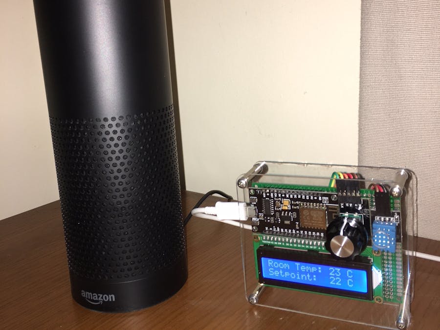
My current home automation system (Insteon) allows me to manually turn my heating system on and off via a micro switch wired to the boiler. However, I didn't have a thermostat in place that would shut it off once it reached a desired temperature, nor turn off when I left home and I didn't want to pay £250 for a Nest Thermostat. So I decided to make my own with a few components I had lying around and integrating them to my existing home automation system (Insteon and HA Bridge running on a Raspberry Pi).
The code can be amended to work with other on/off IoT switches depending on user requirements (Line 238 onwards in the code provided). WARNING! If you are to hard-wire any controls to your boiler / heater, please take all the relevant precautions.
The code is not pretty/perfect and would probably need improvement, but it works!
By linking this project with IFTTT, the options are incredible! So far, I have geo-fenced my phone to trigger the system to power down when I leave the house (instructions are the bottom). One could also set a trigger the thermostat via IFTTT to increase the temperature on your way back from work.
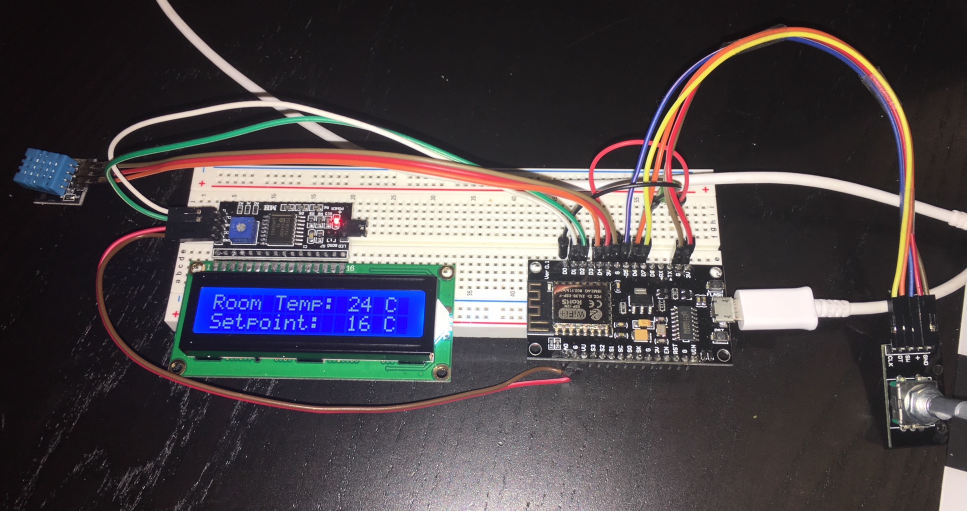
Basic Setup Steps- Wire everything on a breadboard and test it works:
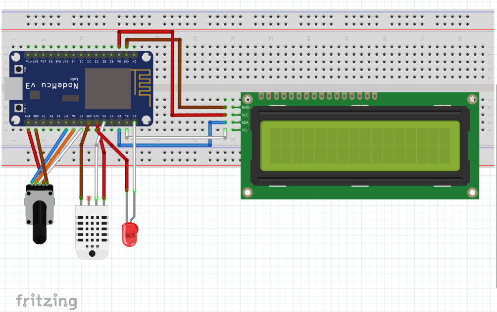
The wiring is pretty simple (photo below - looks more complicated than what it really is). I've also provided the pin connections from the NodeMCU to the components (DHT11 sensor, rotary encoder, and LCD screen).
Once the wiring is done, the NodeMCU can be flashed with the code (DON'T forget to customise the code to suit your needs!). Note that there are some libraries that need to be added and finding the address of the LCD display (which needs to be amended in the code under line 27).
Liquid Crystal Library for LCD: https://bitbucket.org/fmalpartida/new-liquidcrystal/wiki/Home
- If all went well, you should be able to view the web server by using the device's IP address and port. It should look like the image below. Test that the buttons are changing the parameters on the LCD screen when pressed.
- Solder the components to the universal board:
In order to activate the voice control, you will need to take the HTTP command from the web server and program the HA Bridge so that Alexa can discover it.
I've not provided instructions on how to set up the HA Bridge, but this can be done by following the links provided below. HA Bridge runs on a Raspberry Pi.
Once the HA Bridge is set up, simply ask Alexa "Discover my devices". If everything went well, it should recognise the new devices. Once done, ask Alexa to turn on the heating!
IFTTT: Geo-fencing (Optional)
Ever walked away and left the heating on? It's happened to me, many times! With a simple IFTTT recipe using the Maker channel (now Webhooks) you can link a device (i.e. you phone) to trigger a recipe when you exit a certain area.
IF: search for "Location", adjust geo-fence to suit needs.
THAT: "Webhooks". You will need the WAN IP address of your router, the port number assigned to the thermostat and the "off" command, then use POST - e.g. "http://199.199.199.199:305/OFF"
Final Setup VideoBreadboard Setup
D0 (GPIO 16) to - on LED. + on LED can be connected to any 3v output
D1 (GPIO 5) to SDL on i2c on LCD display
D2 (GPIO 4) to SDA on i2c on LCD display
D4 (GPIO 2) to sense on DHT11 sensor
3V to DHT11 sensor +
G to DHT11 sensor ground
D5 (GPIO 14) to SW on rotary encoder
D6 (GPIO 12) to DT on rotary encoder
D7 (GPIO 13) to CLK on rotary encoder
G to GND on rotary encoder
3V to + on rotary encoder
VUSB (VU) to + on i2c for LCD display (this is 5v output. For NodeMCU v2, it would be VIN pin)
G to GND on i2c for LCD display


Comments