


Hardware components | ||||||
| × | 1 | ||||
 |
| × | 1 | |||
| × | 1 | ||||
| × | 1 | ||||
 |
| × | 1 | |||
Software apps and online services | ||||||
| ||||||
| ||||||
| ||||||
 |
| |||||
Hand tools and fabrication machines | ||||||
 |
| |||||
 |
| |||||
 |
| |||||
Many sensor signals are not ready to be connected directly to a microcontroller ADC. A sensor may produce a small, noisy, or relatively high-impedance analog signal, so a simple ADC connection can make the measurement less stable or less useful.
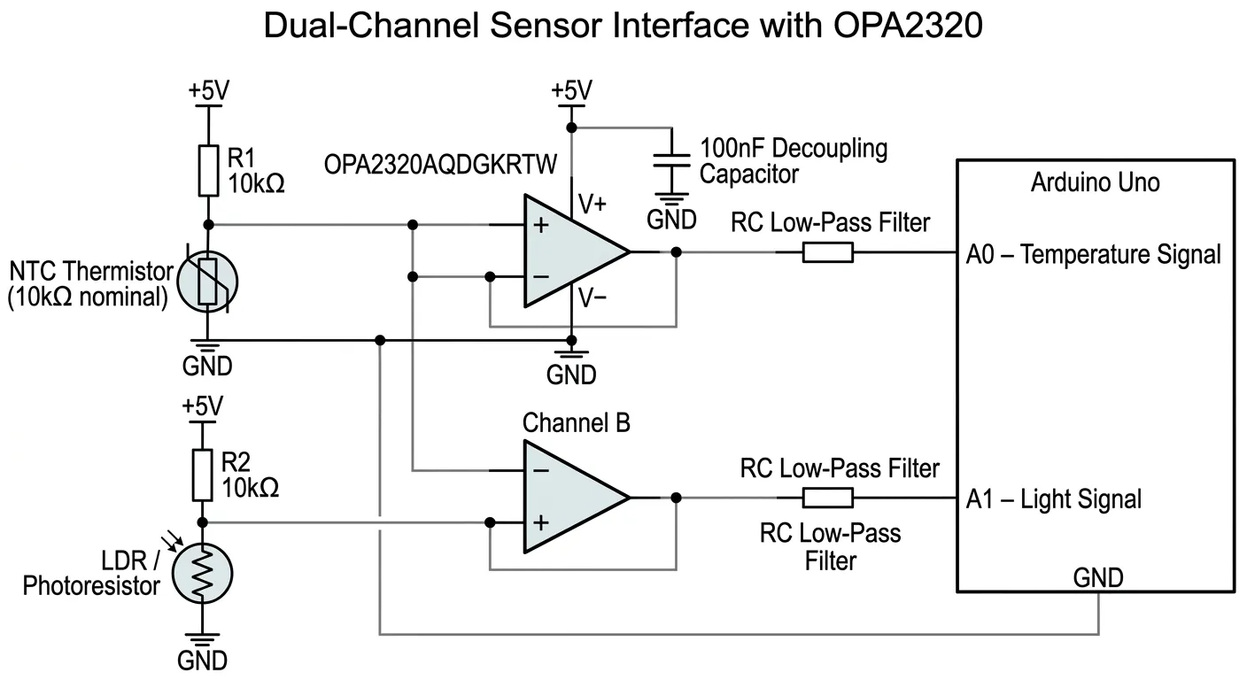
This project explores a compact dual-channel analog front end built around the OPA2320AQDGKRTW precision operational amplifier. The goal is to condition two different sensor signals before sending them to the ADC of an Arduino Uno.
The first channel is used for an NTC thermistor temperature sensor. The thermistor and resistor form a voltage divider that produces an analog voltage related to temperature. The OPA2320 is used to buffer and condition this signal before it reaches the MCU ADC.
The second channel uses a photoresistor (LDR) to measure changes in ambient light. Its voltage-divider output is processed through the second amplifier channel and then connected to another Arduino ADC input.
The basic signal path is:
Sensor → Voltage Divider → OPA2320 → Arduino ADC → Serial Monitor
The two channels make it possible to observe how the same dual-channel op-amp can be used to interface different types of analog sensors with a microcontroller.
How It WorksThe OPA2320AQDGKRTW provides two independent operational amplifier channels in a single package. In this prototype, one channel is assigned to the temperature-sensing path and the other to the light-sensing path.
The Arduino Uno periodically samples the conditioned analog voltages through its ADC inputs. The firmware converts the ADC readings into useful measurement values and sends the results to the Serial Monitor.
During testing, the sensor conditions can be changed manually—for example, warming the NTC thermistor or changing the amount of light reaching the LDR. The corresponding changes in the conditioned analog signals and ADC readings can then be observed.
Why I Made ItI wanted to build a simple but practical example of the analog signal-conditioning stage that is often placed between a sensor and a microcontroller.
Instead of using the OPA2320 only as a standalone component demonstration, this project focuses on the complete signal chain and the practical measurements that matter when designing a small sensor interface: sensor output, analog conditioning, ADC readings, and response to changing input conditions.
The resulting prototype can also serve as a starting point for other low-level analog sensor interfaces where buffering, filtering, or additional signal conditioning is required.
TestingThe prototype will be tested by monitoring both sensor channels through the Arduino Serial Monitor. Measurements will be taken while changing the temperature and ambient light conditions to verify that the ADC readings follow the sensor inputs.
Photos of the breadboard circuit, close-up views of the OPA2320 section, and test results will be included to show the complete hardware implementation


Comments