For this activity, a software-based comparator was implemented using the MCU to read an analog voltage and determine whether it was above or below a reference voltage. A fixed reference voltage was created by dividing the 3.3V supply with resistors, while a potentiometer provided the variable input voltage for comparison.
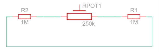
Step-by-StepTwo 1MΩ resistors are connected in series on the breadboard from the 3.3V rail to ground. The midpoint between the resistors is connected to VCompNeg (PA2 on the MCU), creating a fixed reference voltage of approximately 1.65V. The potentiometer is connected to VCompPlus and provides a variable input voltage ranging from 0V to 3.3V, which is monitored by the MCU.
Figure 1. Breadboard Circuit Setup for the Software-Based Voltage Comparator
Setting up the voltage divider and potentiometer on the breadboard before testing the software-based comparator.
- Running the polling version
First I loaded the polling firmware. The code just keeps checking the ADC value in a loop and flips the LED when the input crosses the reference. I measured the 3.3V rail with a multimeter: it came out to 3.319V, so the expected threshold was around 1.660V. The LED actually switched at 1.733V, which is close enough given tolerances in the components.
while (1)
{
HAL_ADC_Start(&hadc1);
HAL_ADC_PollForConversion(&hadc1, HAL_MAX_DELAY);
adcValue = HAL_ADC_GetValue(&hadc1);
if (adcValue > threshold)
{
// LED on or color change
}
}
STM32CubeIDE polling code block
- Switching to interruptsI changed the #if flag in main.c to switch from polling to interrupt mode. The MCU now uses the Analog Watchdog feature, which triggers an interrupt automatically the moment the voltage crosses the threshold. The threshold itself didn't change, only how the MCU detects it. Polling burns CPU cycles constantly checking; interrupts let the processor do nothing until it needs to react.
Figure 1: ADC1 Configuration and Analog Watchdog Settings
This screenshot shows the ADC1 setup in STM32CubeMX. The Analog Watchdog is enabled for Channel 0 (PA0) with a high threshold of 2048 and low threshold of 0 to trigger interrupts when readings exceed these limits.
void HAL_ADC_LevelOutOfWindowCallback(ADC_HandleTypeDef *hadc) {
if(hadc->Instance == ADC1) {
adc_value = HAL_ADC_GetValue(hadc);
ADC_AnalogWDGConfTypeDef watchdog_config = {0};
watchdog_config.WatchdogMode = ADC_ANALOGWATCHDOG_SINGLE_REG;
watchdog_config.Channel = ADC_CHANNEL_0;
watchdog_config.ITMode = ENABLE;
if(state == 0) {
HAL_GPIO_WritePin(GPIOF, GPIO_PIN_11, !GPIO_PIN_RESET);
state = 1;
watchdog_config.HighThreshold = 4095;
watchdog_config.LowThreshold = 2035;
} else {
HAL_GPIO_WritePin(GPIOF, GPIO_PIN_11, !GPIO_PIN_SET);
state = 0;
watchdog_config.HighThreshold = 2048;
watchdog_config.LowThreshold = 0;
}
HAL_ADC_AnalogWDGConfig(hadc, &watchdog_config);
}
}
TheHAL_ADC_LevelOutOfWindowCallback function
- Adjusting the threshold to 1V
Last part was modifying the resistor divider so the LED switches at 1V instead. I recalculated the resistor ratio for a 1V reference and updated the circuit. Tested it with a multimeter while turning the pot, and it switched right around 1V as expected.
Documentation
Image source: Regine Bermudo
note: The image were provided by Regine Bermudo with her consent, as we collaborated on this individual assignment.






Comments