

Hardware components | ||||||
 |
| × | 1 | |||
| × | 1 | ||||
| × | 1 | ||||
Software apps and online services | ||||||
 |
| |||||
| ||||||
Hi guys, I already have a lot of DMX controlled lights inside the house but also wanted to have some outside. As these RGB DMX lights are rather expensive (one ca. 200 - 300€) I searched for alternatives.
What I found was these really cheap RGB LED floods with IR control units. These are around 8€ / 10W RGB.
So, all I had to do is to convert these to understand DMX.
To keep the costs and needed PCB space down, all 5 floods have only one Arduino brain in a separate box. Each light has a 3 channel PWM triggered constant current source PCBs and a D-Sub 9 connector cable. This PCB fits perfectly into the small compartment on the bottom of the light. Each channel for the LED is set to 350mA.
All 5 lights are connected to a central box with the arduino and the wireless DMX receiver
Inside this box are:
- 12V 3,5A power supply
- 12V - 5V mobile phone charger
- Ardunino Nano on own PCB for DMX (RS485) converter
- Ardufruit 16 channel PWM extrension over I2C
- Wireless DMX receiver
- Distribution PCBs for D-Sub ribbon cables
- A lot of hot glue to make it water tight
It survived so far 3 weeks in heavy rain, it seams the box and the sealing are water tight.
The PCB where I mounted the Nano is universal for all my DMX projects, it can convert the DMX bus signals to the Ardunio and also is a breakout for the I2C bus and / or all 6 PWM channels with MosFETs (BUZ11). I also used it with the MosFETs to update inside lamps to DMX.
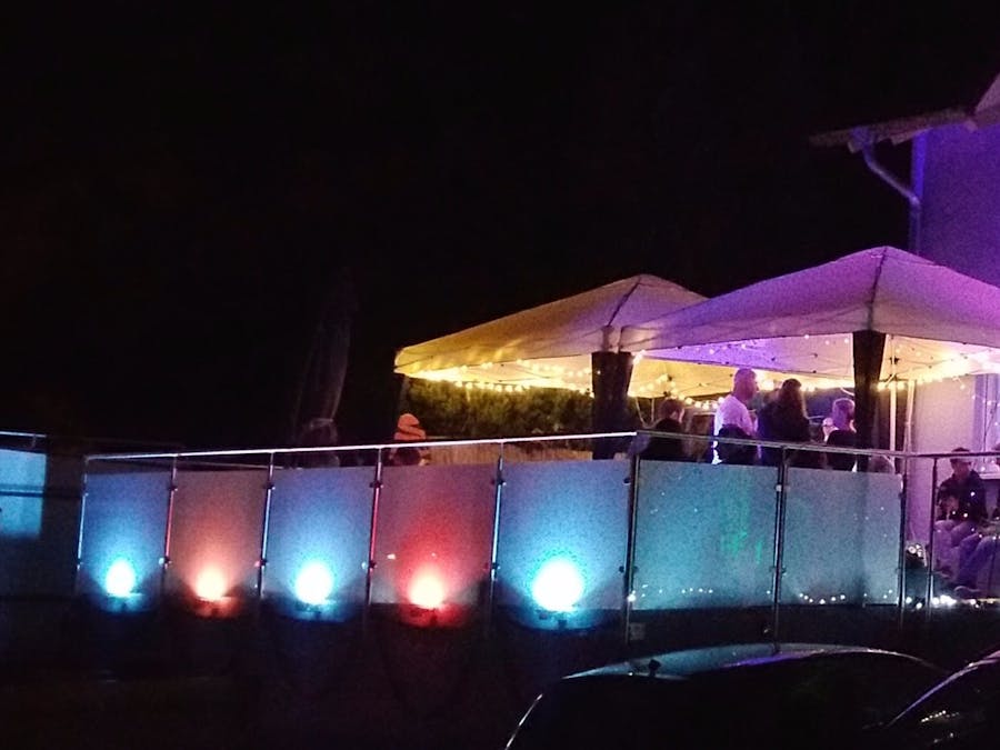
So all togehter results in 5 individual controlled lamps (here for my glass railing) which are controlled via wireless DMX over a PC / mobile phone.
In the downloads you'll find the eagle-files for the PCBs, my copy&paste Arduino sketch and the definition-file for the lamp in the PC control software Freestyler.
The DMX-Adresses are hard-coded to start address 200 and then 5x 3 channels R, G and B without any dimmer channel.
In the Arduino-Sketch i had to manipulate the values for the red channels, as the red LED is much brighter than green and blue and therefore would not mix to pure white.
Alternatively there's one sketch for testing / bugfixing where you can set the RGB values directly via the Ardunio IDE terminal
Altogether the total cost for 5 lamps are around 110€, all parts (exepts lights) sourced through Reichelt.de, all PCBs made by platinenbelichter.de (big recommendation!)
Feel free to modify or optimize all!
Bye,
Sebastian


Comments