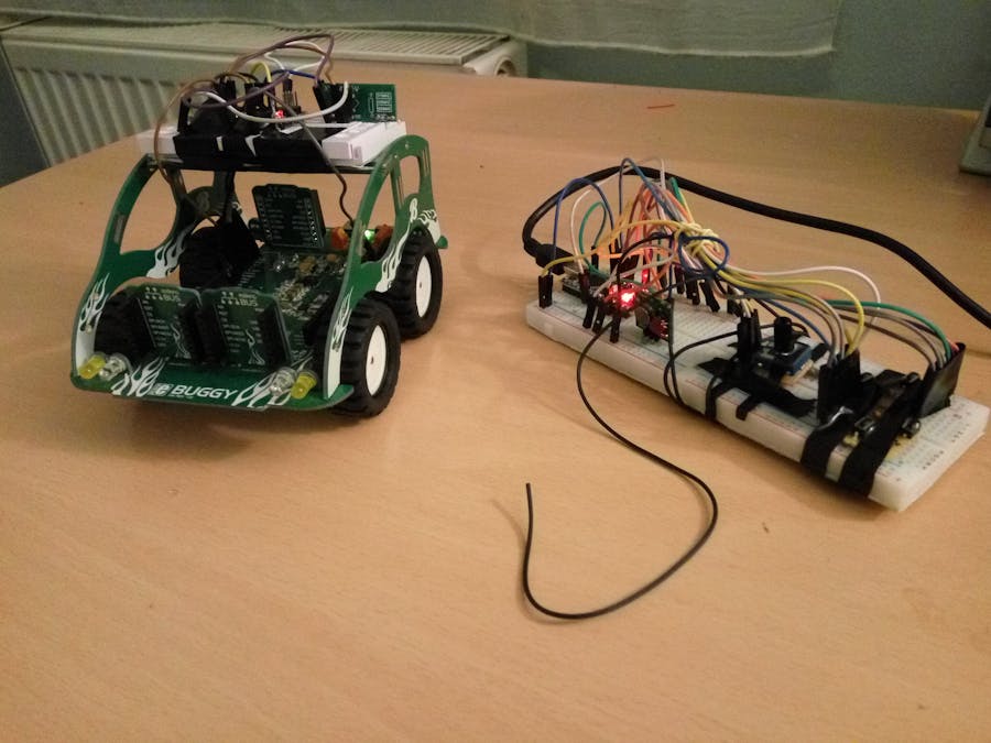
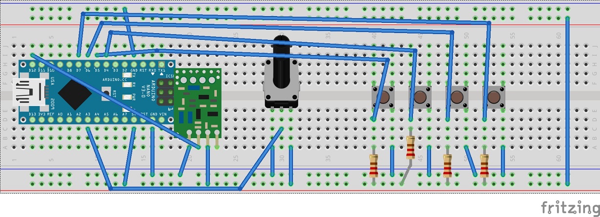
brzi
Published

Rf controlled buggy

RC buggy controlled with 433MHz RF modules.

BeginnerShowcase (no instructions)45 minutes7,510
Rf controlled buggy

Things used in this project

Hardware components

Arduino Nano R3
Arduino Nano R3
×2
XY-MK-5V / XY-FST 433Mhz Rf Transmitter and Receiver
×1
Rotary potentiometer (generic)
×1
Pushbutton switch 12mm
SparkFun Pushbutton switch 12mm
×4
Resistor 10k ohm
Resistor 10k ohm
×4
Jumper wires (generic)
×1
MikroE buggy (optional)
×1
Solderless Breadboard Full Size
×1
Solderless Breadboard Half Size
×2
Texas Instruments SN754410
×1
DC motor (generic)
×4

Story

Read more

Schematics

Transmitter

Transmitter used to send instructions and data to the receiving side. Made in Fritzing.

Transmitter schematic

Schematic for the transmitter

Code

Transmitter

C/C++
Consists of 4 buttons, potentiometer, XY-FST 433MHz RF transmitter and one arduino nano. XY-FST is connected to the pin 12 of the arduino.
#include <RH_ASK.h>
#include <SPI.h>

RH_ASK driver(2000,12,12,10,true);//Data pin connected to pin 12

byte sensorArray[1];
void setup(){
  if(!driver.init());//Must not be left out, otherwise the library will not initialize
}

void loop(){
  //Start the pwm signal (on receiver side) when a button is pressed
  while(digitalRead(4)==LOW)
    send("1");
  while(digitalRead(5)==LOW)
    send("2");
  while(digitalRead(6)==LOW)
    send("3");
  while(digitalRead(7)==LOW)
    send("4");
  sensorArray[0]=0;//Terminate the pwm signal (on receiver side) when no button is presed
  sensorArray[1]=analogRead(A3)/4;//Readings from the potentiometer, rf modulators only work by sending bytes to receivers
  driver.send((uint8_t *)sensorArray, 2);//Send the array, 2 is the number of bytes in the array
  driver.waitPacketSent();//Wait for the packet to be sent
}

void send (char *msg){
  driver.send((uint8_t *)msg, strlen(msg));
  //driver.waitPacketSent(); Not used because there is no need for it
}

Receiver

C/C++
Consists of mikroe buggy (optional), XY-MK-5V 433MHz RF receiver and arduino nano. XY-MK-5V is connected to the pin 12 of the arduino. Pin 3 is connected to the PWM A pin on the vehicle, Pin 6 on PWM B, Pin 5 on PWM C and Pin 11 on PWM D.
#include <RH_ASK.h>
#include <SPI.h>

byte pwm;//pwm value for the mottors
RH_ASK driver(2000,12,12,10,true);//Data pin connected to pin 12

void setup(){
	if(!driver.init());//Must not be left out, otherwise the library will not initialize
}

void loop(){
	uint8_t buf[RH_ASK_MAX_MESSAGE_LEN];//array of received values are stored here
	uint8_t buflen = sizeof(buf);//size of the array, needed by the library
	if(driver.recv(buf, &buflen)){//if the signal is received
		pwm=85*((float)buf[1]/255)+170;//buf[1]=sensorArray[1], values adjusted for specific motors on this vehicle(values range from 170 to 255);
		while(buf[0]=='1'){//buf[0] in this case corresponds to send("1") in the transmitter
			analogWrite(6,pwm);//forward
			analogWrite(11,0.3*pwm);//adjusted for moving to a side
			if(driver.recv(buf, &buflen)=='0')//buf[0] in this case corresponds to sensorArray[0] in the transmitter,when the button is released, pwm's are set to 0
				break;
		}
		while(buf[0]=='2'){
			analogWrite(11,pwm);//forward
			analogWrite(6,0.3*pwm);//adjusted for moving to a side
			if(driver.recv(buf, &buflen)=='0')
				break;
		}
		while(buf[0]=='3'){
			analogWrite(6,pwm);//move 
			analogWrite(11,pwm);//forward
			if(driver.recv(buf, &buflen)=='0')
				break;
		}
		while(buf[0]=='4'){
			analogWrite(3,pwm);//move
			analogWrite(5,pwm);//backward
			if(driver.recv(buf, &buflen)=='0')
				break;
		}
		analogWrite(3,0);//stop all pwm's
		analogWrite(5,0);//when not in
		analogWrite(6,0);//any of the loops
		analogWrite(11,0);
	}
}

Credits

brzi

brzi

5 projects • 40 followers

Comments