

Hardware components | ||||||
 |
| × | 1 | |||
_ztBMuBhMHo.jpg?auto=compress%2Cformat&w=48&h=48&fit=fill&bg=ffffff) |
| × | 1 | |||
 |
| × | 1 | |||
 |
| × | 1 | |||
Heading: System Architecture
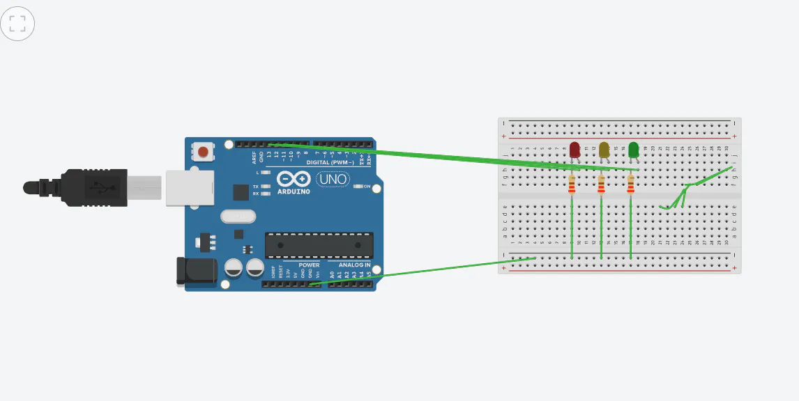
Text: The firmware configures digital pins 11, 12, and 13 as outputs to drive a Red, Yellow, and Green LED array. It utilizes non-blocking logic to transition the system sequentially through active states.
Heading: Timing Logic
Text: Maintains a steady 5000ms window for the Red (Stop) and Green (Transit) phases, and a 2000ms window for the Yellow (Caution) phase.


Comments