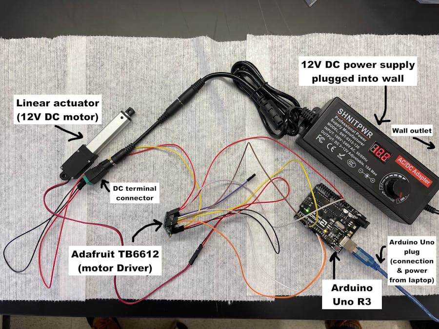
For this project, I wanted to control a motor, specifically a linear actuator (with linear motion), using a 12V power supply.
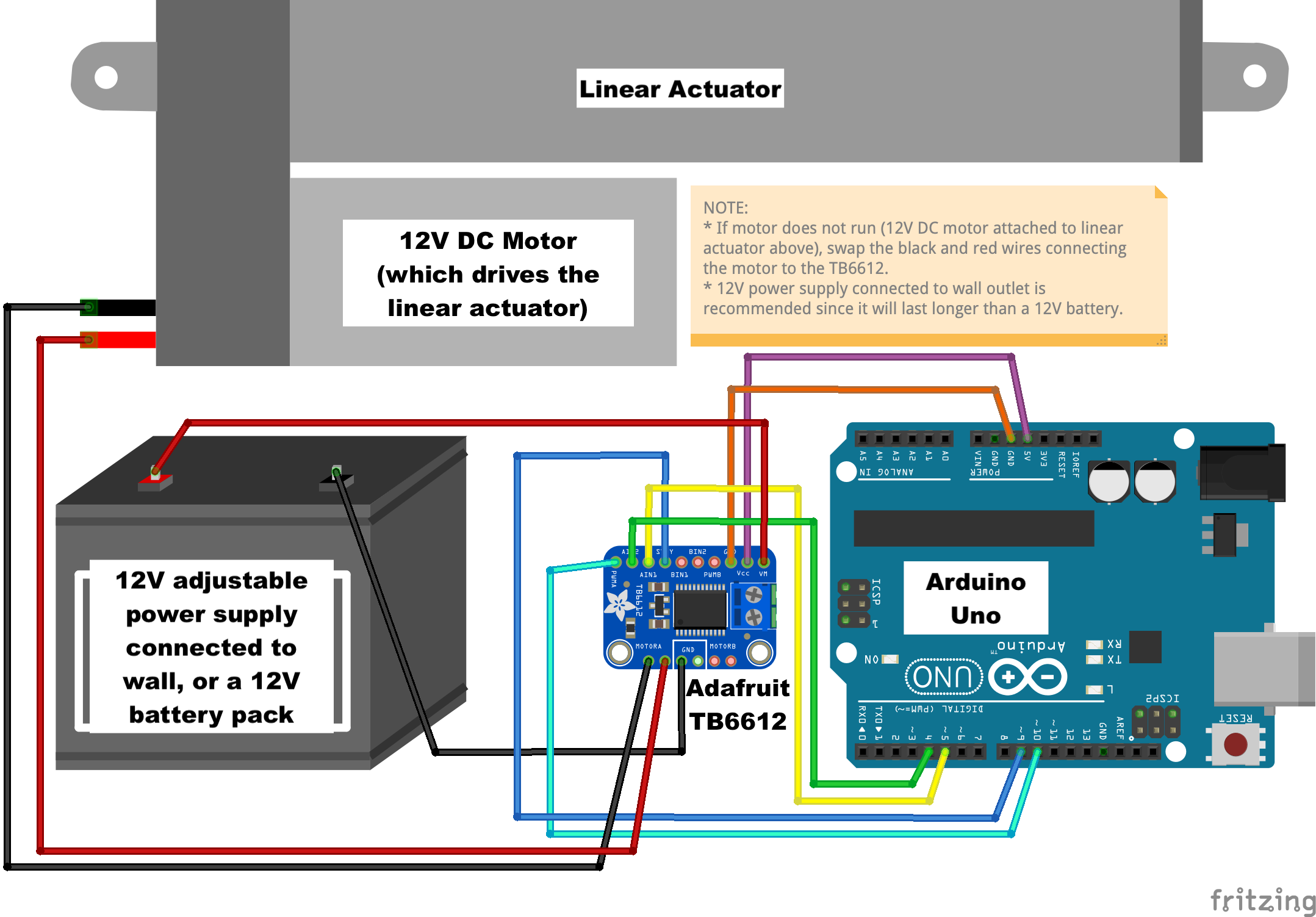
For this to work, I found that I needed an Adafruit TB6612 motor driver breakout board in addition to the Arduino Uno board. This driver can control 2 DC motors, or 1 stepper motor (a DC motor usually has 2 wires, while a stepper motor has more than 2 wires coming out of it).
Since I had difficulty finding a good Adafruit wiring diagram for a DC motor (with two wires coming out of it), I've made one here for you with Fritzing!
For this tutorial, I am using a 12V DC motor (a stepper motor would also work but would require different wiring, explained on the Adafruit.com TB6612 tutorial). However, you could use my setup for any DC motor that takes between 5V to 12V power voltage, as long as you properly adjust the power supply voltage level. It can be handy to use an adjustable external power supply (that comes with a DC terminal connector) like I did!
You are likely to run into issues if your motor is not wired correctly. If the motor isn't moving, try swapping which of the wires gets connected to which of the two MOTORA pins.
In the end, for this project, you will use an Arduino, TB6612 motor driver, and a 12V external wall power supply to control your motor and/or linear actuator.

_ztBMuBhMHo.jpg?auto=compress%2Cformat&w=48&h=48&fit=fill&bg=ffffff)


Comments