

Hardware components | ||||||
 |
| × | 1 | |||
 |
| × | 1 | |||
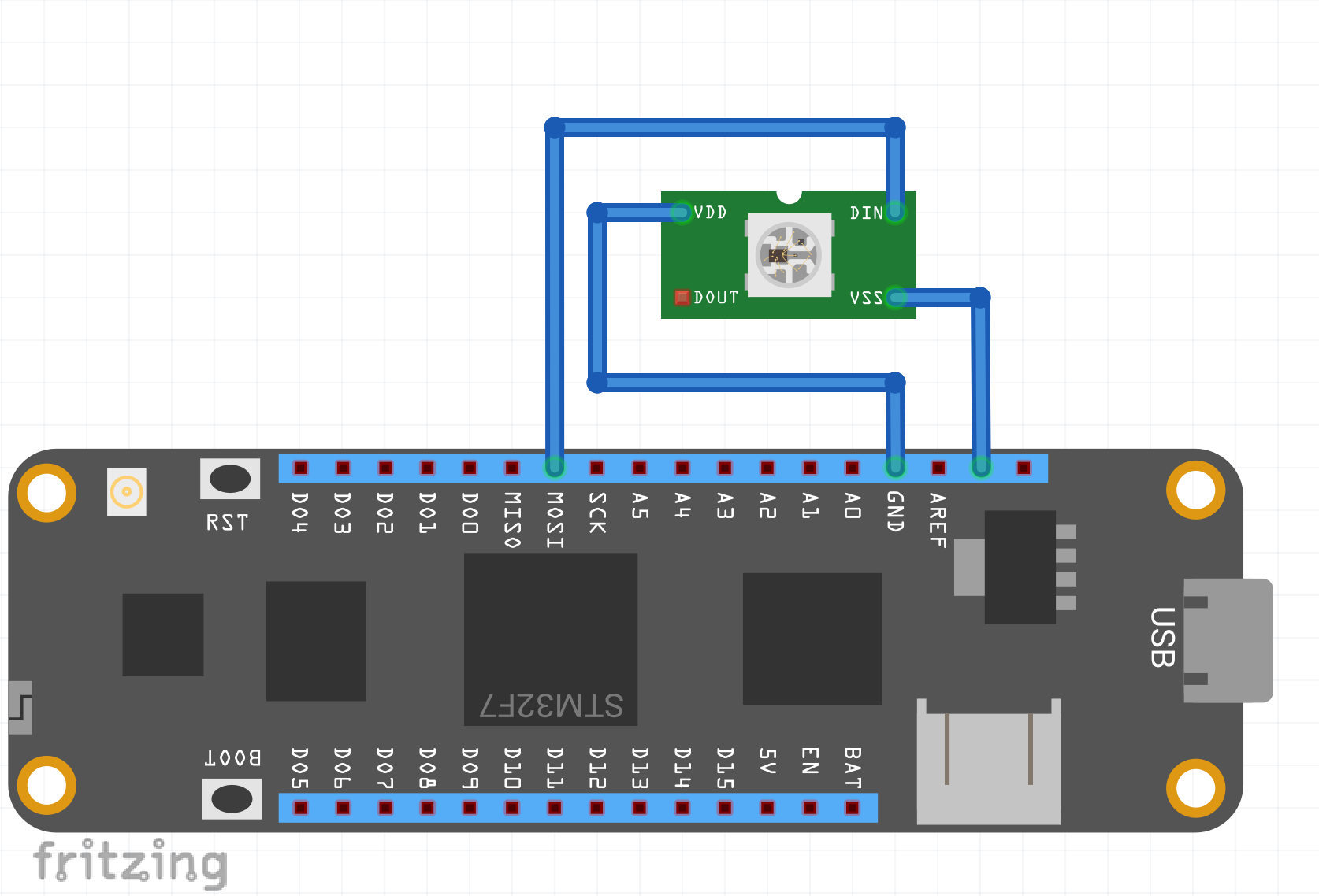
- Hook up WS2812 LEDs to +3v3, GND and COPI (Formerly MOSI) on the Meadow
- Get a copy of the code provided from GitHub
- Modify the
Initializemethod to specify the number of LEDs you have (This project uses 10 and was powered off the USB port on a laptop). - Modify the
Runmethod to make calls toSetColorsandUpdateas appropriate
- Setup for the Meadow CLI - That's Here
- Setup for.NET or C#
The idea is to use the COPI signal from the SPI bus to signal the various high and low periods. Some cheats that might be helpful:
- As long as T0H and T1H are in specification, you may be able to get away with T0L and T1L exceeding the maximum (provided that this period is less than the minimum for RESET.) This is naughty, but potentially helpful.
Configuring the SPI data rate to 3 MHz, we can generate pulses that are a multiple of 333 ns. So when we need to send T0H pulses we use a single one bit in the SPI data stream, and to send T1H pulses we use two one bits, yielding pulse widths of about 333 ns and 666 ns respectively.
Taking advantage of the cheat above, we have longer T0L and T1L timings partially due to inter-byte SPI delay (one extra 333 ns interval of low) and partially due to data packing optimization (by encoding a single bit of pixel data as four bits of SPI data, the data conversion is simplified.)
We have not seen any situation where the RESET threshold is exceeded. Based on our understanding of the underlying Nuttx SPI implementation, they are not using DMA, but they are keeping the 32 bit FIFO register full, so if there is any condition where the Nuttx SPI write loop is interrupted (chip interrupt for instance), there should not be any data alteration if control returns within 32 * 330 ns.
The way the current system works is that you specify the number of LEDs and the Ws2812 class allocates a byte array to store the encoded data. When you call the SetColors method, you provide an IEnumerable that produces Color structures, and then the R, G and B values from that structure are converted to the on-the-wire representation. The Update method simply does a SPI transmission of the final encoded data.
Each LED gets its 3 R G and B values as 24 bits after the conversion described in the next section. For a 10 LED string, you're looking at 240 bits. The WS2812 works by passing all 240 bits of data down the string, taking the nth 24 bits depending on its location in line and passing the data along. This is how we are able to address them individually.
Let's say we need to figure the bits to send a Red to a single pixel (255, 0, 0) on (R, G, B) we'd send (0b1111_1111, 0b0000_0000, 0b0000_0000). However, that is just part of the story. We need to send pulses that fall in the specifications for T0 and T1.
The COPI line can only send even-sized even spaced pulses that are multiples of its clock signal, not these unequally sized pulses that the WS2812b sequencing chart expects. Therefore, the clock signal needs to be set such that it can send pulses that divide nicely into these WS2812b pulse width requirements. When we do that, we find that 3 MHz works nicely and that lets us send 1 high pulses followed by 3 cycles of 0 for a WS zero and 2 cycles of high pulses followed by a cycle of 0 for a WS 1.
Because it takes us 4 clock cycles (4 bits) to communicate a one or a zero in WS2812, we can send bytes (2 1s or 0s) which makes this simple to program. If we utilize the Write method on the Meadow.Hardware.ISpiBus we're able to send bytes that represent pairs of bits in our RGB binary encoding.
In our setup, we take our Red, Green, and Blue values each, split off bits 2-by-2 starting at the most significant bit, then map them to a WS2812 byte depending on if the two bits are 00, 01, 10, or 11. Since we have this convenient representation of a 4 element array, we can store the WS2812 bytes in them. For example, a 1 bit in the microcontroller has to become a 0b1100 nibble so a 11 pair has to be a 0b1100_1100 (or 0xCC if you're short on time).
We did discover a quirk with the STM32F777 on board however which throws a wrench into this theory. The SPI data line that is responsible for sending data is held high or low between bytes depending on whether the most significant bit of the byte it just sent. So the data line for a 0x88 would be high (most significant bit 1) after the transmission. This was causing some data corruption as the next byte would receive some of the high signal, causing the WS2812 to misinterpret the data.
The solution was shifting the WS2812 bytes right by one so the leading most significant bit is always 0 allowing for consistent positioning of the data line between bytes. If you see the code, and were following along, you may have been expecting the WS2812 bytes to be 0x88, 0x8C, 0xC8, and 0xCC but right shifting is a divide by 2 operation so you'll actually see 0x44, 0x46, 0x64, and 0x66.
The setup and deployment of this project is very simple. First, Connect your power and ground wires from the first LED on a neopixel strip to the 3.3V and GND pins on the Meadow respectively. Next connect your data line to the COPI pin on the Meadow.
The diagram represents the connection to the first pixel.
⚠️ Be sure to check the polarity of the strip! ⚠️
Some strips come with indication arrows. The arrows should be pointing away from the Meadow Board. If you follow the wire from the board to the strip and the arrow points back, you need to go back and plug in your strip from the other end.
Next clone the repository, navigate to Meadow.Ws2812/MeadowApp.cs and modify the Setup code like so.
public override Task Initialize()
{
    // change this to match your LED strip LED count
    int ledCount = 10;

    _ws2812 = new Ws2812(Device.CreateSpiBus(new Frequency(3.2, Frequency.UnitType.Megahertz)), ledCount);
    return base.Initialize();
}
Then to send colors out, modify the Run code like so.
public override Task Run()
{

    // change colors here
    // position in this array reflects position on LED strip
    var colors = new Color[] {Color.Red, Color.Orange, Color.Yellow, Color.Green, Color.Blue, Color.Indigo, Color.Violet, Color.White, Color.Black, Color.Brown};
    _ws2812.SetColors(colors);
    _ws2812.Update();
    return base.Run();
}
Save the file and from a command prompt in the Meadow.Ws2812 directory run the following. You should have your Meadow board hooked up to your light strip and plugged into your PC at this point.
dotnet build
meadow app deploy --file Meadow.Ws2812/bin/Debug/netstandard2.1/App.dll
After a minute or so you should see your LED strip light up.
Wrapping UpWe just walked through the theory of operation for the WS2812 protocol, a brief intro to bit banging, and the how to hello world WS2812 lights from a Wilderness Labs Meadow F7 Micro. We hope you found this deep-ish dive into the WS2812 protocol enlightening (sorry).


Comments