

Hardware components | ||||||
| × | 1 | ||||
Software apps and online services | ||||||
 |
| |||||
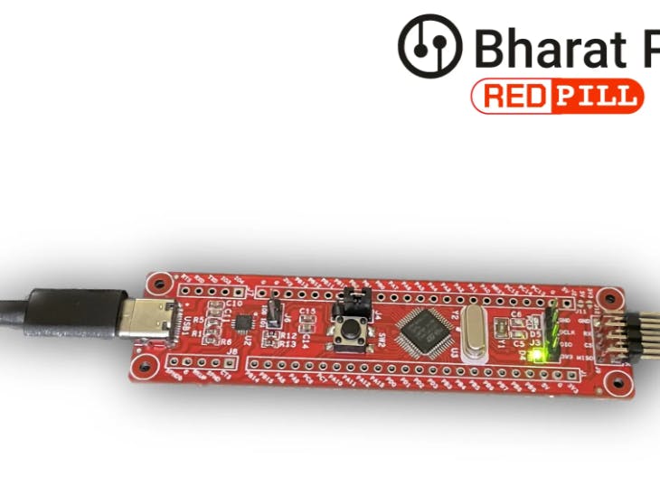
The "RedPill" in Bharat Pi is a development board designed for prototyping Internet of Things (IoT) projects. It is based on the STM32G0 series microcontrollers (MCUs) from STMicroelectronics, specifically the STM32G071CBT6TR.
Bharat Pi RedPill STM32 Development Board
The RedPill's key feature is that it provides access to all 48 pins of the MCU. This allows you to connect a wide variety of sensors and other devices to the board for your IoT projects.
Here are some of the other features of the Bharat Pi RedPill:
- Low-power consumption
- Compact size
- Breadboard compatible
The RedPill is a good option for developers who are looking for a versatile and affordable development board for their IoT projects. It is especially well-suited for projects that require low power consumption or a small form factor.
Supplies- STM32CubeMX,
- STM32CubeIDE,
- STM32CubeProg,
- STSW-LINK007
- Jumper wire
And you have to buy an ST-LINK V2
Step 1: Create New Project Using STM32CubeMX- Run STM32CubeMX tool.
- Click New Project or Menu -> File -> New Project.
- Please search for the commercial part number "STM32G071CBR" and select the appropriate module.
- Click Start Project to continue.
- Answer YesInitialize all peripherals with their default Mode. popup.
- Please navigate to the pin labelled PC13 and select it as a GPIO output.
The corresponding pins PA13 and PA14 are assigned and configured automatically.
- When a board is selected, STM32CubeMX allows automatically the pinout setting for the board with the pin assignments for the communication interfaces, LEDs, and other functions.
Switch to the Project Manager tab to configure the project. In the Project tab:
- Fill the Project Name and Project Location fields
- Set Toolchain/IDE to STM32CubeIDE.
In the Code Generator tab, ensure that the following options are checked:
- In STM32Cube Firmware Library Package section: Copyall used libraries into the project folder.
- In Generated files section: Keep user code when regenerating the C code option, which only applies to the user sections within the STM32CubeMX generated files.
To generate the project in STM32CubeIDE:
- Click on Generate Code.
- 📷
- Click on Open Project to open the project with STM32CubeIDE.
- 📷
In STM32CubeIDE, from the Project Explorer tab, open the main.c file, in Src folder and add the adequate functions for the LED blinking, using HAL functions with the STM32CubeL4 firmware package.
Step 6: Build the ProjectClick on the project from the project explorer, then right click and select Build Project, to compile the project (or click on Build button on the toolbar).
Step 7: Verify the Output in Console Window


Comments