


Hardware components | ||||||
 |
| × | 1 | |||
| × | 1 | ||||
| × | 1 | ||||
Software apps and online services | ||||||
| ||||||
Hand tools and fabrication machines | ||||||
| ||||||
| ||||||
| ||||||
| ||||||
In France, on the 433 MHz ISM band, the ANFR enforces a maximum transmission power of +10 mW ERP (≈ +10 dBm); any attempt to increase range by raising the output power is illegal. However, the LoRa modulation was designed with very high sensitivity in reception (up to –137 dBm in SF12 / 125 kHz), which corresponds to a radio link budget of at least 150 dB. Under optimal propagation conditions (open field with no obstacle, line of sight), this link budget is enough to span tens of kilometers.That’s why a repeater is necessary: to fully exploit the available link budget and reach long distances, the transmitter’s location must be carefully chosen. By placing the repeater at a high point, a hill, tower, or treetop with a clear line of sight, a single module can cover several tens of kilometers without exceeding the legally allowed transmission power. This strategy is at the heart of the LoRaTube concept: keeping a compliant, very low-cost, discreet, and autonomous transmitter (> 5 years), while maximizing coverage through optimal placement.
https://hackaday.io/project/203696-loratube
Why LoRaTube?Because this project does not use solar panels — it relies instead on alkaline batteries housed in a PVC tube. Most LoRa repeaters (whether DIY or commercial) depend on solar panels paired with lithium-ion batteries, MPPT regulators, and charge management circuitry.
This leads to:
- a high cost (often €150 or more)
- some mechanical and electronic fragility;
- a bulky footprint, making the device more visible and attractive to theft;
- and above all, poor reliability in winter: in temperate climates, solar production can drop fivefold between summer and winter, forcing designers to oversize the system just to maintain basic service.
What We’re Proposing – Design Objectives
The goal is to build an ultra-discreet, robust LoRa repeater using widely available and very low-cost materials — specifically alkaline D-size (LR20) batteries and standard 40 mm / 50 mm PVC pipes for the enclosure and mast. The system is designed to run for multiple years in outdoor environments, including locations with no sunlight (under vegetation, in barns, etc.), for under €50 total, including the LoRa module and enclosure.
🔋Power SupplyThe power supply is based on 18 LR20 alkaline batteries (D size) in series, housed in a compact enclosure less than 50 mm in diameter.This battery choice offers several practical advantages: LR20 cells are inexpensive (less than €1 each in most supermarkets) and widely available. Each LR20 battery typically provides 12, 000 to 18, 000 mAh, or 18 to 27 Wh. With 18 batteries, the total energy amounts to approximately 486 Wh, for a total cost of €13.30 (5 packs × €2.66), which translates to just ~€0.024/Wh — a ridiculously low cost compared to lithium alternatives.
For comparison:
- A 18650 lithium cell offers ~11 Wh for ~€4 → €0.36/Wh (15× more expensive)
- A pack of ten flat lithium cells (~52 Wh) costs ~€20 → €0.38/Wh
Wiring 18 batteries in series raises the voltage to 27 V (18 × 1.5 V). The cost per delivered kilowatt-hour remains extremely competitive: around €13/kWh, compared to over €250/kWh for a solar + lithium setup (including MPPT regulator) — a 20× cost advantage.
These batteries also have very low self-discharge (< 1% per year), enabling several years of operation as long as the current draw stays low.
Another benefit: the batteries fit neatly inside a standard 40 mm PVC plumbing tube.There’s just enough room for the LR20 cells and a return wire for GND — with an internal diameter of ~36 mm and the batteries themselves measuring ~33 mm.
Advantages:
- No exposed cables
- A sealed, rugged housing
- Fully weatherproof and mechanically robust
- A long, slim form factor that allows discreet installation in many environments: tree trunks, rooftops, wooden posts, etc.
- And in the event of a nuclear winter? You’ll be glad it runs on LR20s 😄
Using LR20 alkaline batteries may seem like an ecologically debatable choice — their main appeal lies in wide availability and an excellent €/kWh ratio. That said, the picture changes when you consider the following:
- Producing 1 kWh of lithium battery capacity emits 150 to 200 kg of CO₂ (according to recent estimates).
- Typical lithium extraction consumes ~1.9 million liters of water per ton, threatening local aquifers (e.g. the Lithium Triangle, Atacama Desert...).
By contrast:
- LR20 batteries have a self-discharge of ≤ 2–3% per year and a storage life of 5+ years with minimal degradation.
- In France, over 60% of alkaline batteries are recycled, while no effective recycling system exists yet for large-format lithium-ion batteries.
Advantages:This is a simple, primary-chemistry solution (zinc and manganese). While not rechargeable, it offers very long field life and a low environmental impact per useful Wh, especially when yearly energy use is minimal.
The electrical design is also greatly simplified: no charge controller, no MPPT, fewer components — resulting in improved reliability and significantly lower cost.
🛠️ Physical Architecture and Material Choices for a Standalone LoRa Repeater🧰 MechanicsThe mechanical structure is based on a standard 40 mm PVC drainage pipe, whose internal diameter (~36 mm) perfectly fits an LR20 battery and wiring. This clever choice takes advantage of PVC’s strength, availability, and low cost, and minimizes the need for custom 3D-printed parts.
The 3D-printed components are grouped into three functional modules, requiring about 120 g of PLA in total:
1. The tube base, which provides access to the batteries for replacement and ensures contact with the negative terminal of the first battery in the 18-cell series. To avoid mechanical stress, the usual spring is replaced by a brass strip simply soldered to a wire.
2. The compression mechanism, which keeps the battery stack under pressure using three springs and two cylindrical PLA parts. The springs exert around 1 kg of force over 6 mm of travel, with a maximum travel of approximately 15 mm. An M3 screw, whose head moves freely in the upper part and locks with a nut at the bottom, ensures the whole assembly stays in place — even when the system is not under compression.
3. The intermediate part, which makes contact with the positive terminal of the topmost battery and acts as an axial stop to keep the battery stack compressed. Small vent holes at the bottom allow any condensation or water ingress to escape.
4. The top cap, which mechanically supports the PCB via the SMA connector, holds the antenna, and ensures the system is sealed.
It fits onto the top end of the 50 mm diameter PVC tube.
The compression force from the springs, which ensures good contact between the batteries, generates about 3 kgf at the top of the stack for a displacement of ~10 mm. The battery column weighs approximately 2.5 kg, so the load increases linearly — from 3 kgf at the top to nearly 5.5 kgf at the base — ensuring stable contact throughout the stack. This force is negligible compared to the mechanical resistance of an LR20 cell, which is rated at roughly 200 kgf.
Electrical Contact, Oxidation, and Galvanic CompatibilityContact oxidation is a major concern for long-term reliability, especially in humid environments or those subject to temperature variations.The internal connections use 2 mm brass rods, chosen for their conductivity, malleability, and ease of soldering.However, brass naturally oxidizes, which can increase contact resistance over time and eventually cause power loss.
Two mitigation strategies were used to address this:
- Solution 1: Tinning the brass tabsCoating the contact surfaces with a thin layer of tin helps prevent oxidation by chemically stabilizing the surface.This is a standard practice for electrical connections and solder joints.It also helps maintain low contact resistance over time.Galvanic compatibility is good: the potential difference between tin and the zinc-plated steel terminals of LR20 cells is moderate (< 0.6 V), well below the 0.8 V threshold considered safe in non-saline environments.
- Solution 2: Applying silicone grease (dielectric grease)Silicone grease forms a hydrophobic barrier that blocks oxygen and moisture from reaching the metal surface.It is commonly used in electrical connectors to enhance long-term durability.However, it is electrically insulating: it must therefore be applied only around or between contact zones — never directly on active contact surfaces, to avoid impeding conduction.
Using LR20 alkaline batteries in series adds up their individual internal resistances.A fresh LR20 cell typically has an internal resistance of about 0.13 to 0.17 Ω.With 18 batteries in series, the total internal resistance becomes roughly 18 × 0.15 Ω ≈ 2.7 Ω.
Under load, this causes a voltage drop
- At 110 mA (typical transmission with an E22400T22D module), the drop isΔV = I × R ≈ 0.11 × 2.7 ≈ 0.30 V
- At 1.3 A (typical for E22400T33D),ΔV ≈ 1.3 × 2.7 ≈ 3.5 V
These voltage drops reduce the effective input voltage available to the system.Fortunately, in both cases, there’s still a comfortable margin for the buck converter, which only needs to step down to 5 V.
Actual Current Draw from the BatteriesBoth the E22400T22D and E22400T33D modules are powered through a DC/DC buck converter (≈85% efficiency).Assuming an input bus voltage of ~23 V (after subtracting internal drops from the 27 V nominal), the current drawn from the battery pack is:
- E22400T22D (TX at 22 dBm):~110 mA at 5 V → 0.55 W output⇒ Input current ≈ 27 mA
- E22400T33D (TX at 33 dBm):~1.0 A at 5 V (values between 850 mA and 1200 mA depending on datasheet)→ ~5 W output⇒ Input current ≈ 242 mA
These are modest current levels for LR20 cells: 27 mA to 242 mA remains well within the comfort zone of a standard alkaline D cell.An alkaline D cell rated at 21, 500 mAh (at 25 mA discharge) can easily supply these currents over extended periods. Even an older battery typically retains several amp-hours of capacity under low current draw. Delivering ~0.3 A continuously remains well below its nominal capability.
🌡️ Effect of Temperature on Internal ResistanceThe internal resistance of an alkaline battery increases significantly at low temperatures.Slower electrochemical reactions and reduced ion mobility effectively "solidify" the electrolyte, increasing its internal resistivity.
For example, with an Energizer E91 AA cell (similar chemistry), internal resistance increases from about 0.15 Ω at 20 °C to 0.9 Ω at –40 °C.By extrapolation, a new LR20 cell (0.15 Ω at 20 °C) could easily reach 0.4–0.5 Ω at –15 °C, or more as it ages.
This rise in internal resistance reduces the voltage delivered to the modules in cold weather, and decreases the effective ability to provide current spikes.
At –15 °C, we can reasonably estimate LR20 internal resistance to be between 0.3 and 0.5 Ω, leading to much greater voltage drops under load.
For example:
At 110 mA: ΔV = I × R = 0.11 × 2.7 ≈ 0.90 V
- At 110 mA: ΔV = I × R = 0.11 × 2.7 ≈ 0.90 V
At 1.3 A (E22400T33D): ΔV ≈ 1.3 × 2.7 ≈ 10 V
- At 1.3 A (E22400T33D): ΔV ≈ 1.3 × 2.7 ≈ 10 V
This still works — but we’re nearing the limit.At much lower temperatures, we’d likely see brownout resets, suboptimal LoRa transmission power, accelerated battery degradation, etc.
💥 Role of SupercapacitorsTo address this, the design includes two 10 F / 5.5 V supercapacitors connected in parallel, located just under the PCB near the LoRa modules. These components are inexpensive (about €7.50 for five on AliExpress). Their main purpose is to supply energy during radio transmission peaks, offloading the LR20 cells and protecting them from sudden high current draw. (In the upcoming PCB V2, they will also allow the buck converter to be shut off during idle, further reducing standby current — a key factor in achieving multi-year autonomy.)
Indeed, during transmission, LoRa modules can draw peaks over 1 A for several hundred milliseconds (equivalent to ~300 mA from the battery side). Such bursts are stressful for alkaline batteries, especially in cold weather: their internal resistance spikes, causing voltage drops that can trigger microcontroller brownouts if the buck can't keep up. The supercapacitors act as energy buffers, quickly discharging to keep the voltage stable during these bursts. Between transmissions, the batteries slowly recharge the supercapacitors through current-limiting of the buck MAX16956AUBA (500 mA @ 5V i.e. ~120 mA @ 5V).
This current smoothing has several benefits
- Improved performance in cold temperatures (less severe voltage drops)
- Prevention of unwanted brownout resets
- Extended battery life, especially in low-temperature environments
- Reduced electrical stress from pulsed current draws
- Reduced current needed by the buck
Additionally, the output impedance of the buck converter plays a critical role in 5 V rail stability during transmission.During a sudden load spike, the control loop cannot respond instantly — its reaction is limited by bandwidth, output capacitance, and capacitor ESR. The instantaneous voltage drop under load is given by:
Properly sized supercapacitors ensure stable device operation and a steady current during transmission phases.
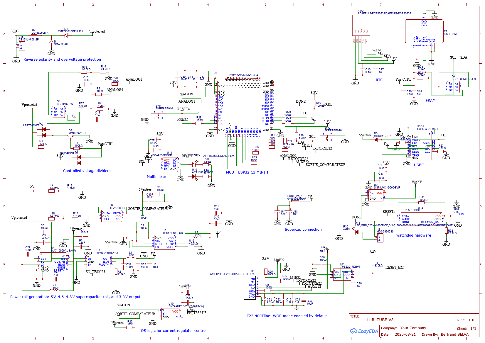
📐 ElectronicsMany thanks to PCBWay for their support. Once again, the manufacturing quality is excellent, and the delivery times are impressively short.It’s a real pleasure to rely on such a dependable partner for projects that require fast, functional prototyping.
Their help made it possible to build the first working version of the device, which I’m sharing here.
The latest files for V3 — the version currently in production with PCBWay — have been uploaded (in the files project).
The archive includes the schematic, Gerber files, Pick and Place data of the V3.
I received the PCB assembled by PCBWay. The board looked great, assembly quality is excellent. After a complete test session, the board already has several straps and modifications. This is the fate of any prototype: direct confrontation with hardware reality.
All critical subsystems (buck, supercap, LoRa, I²C, MCU, watchdog) are validated.Despite the modifications made, the current board enables almost complete firmware development and should reliably support the first real-world tests.
Hardware test program is available on my GitHub: https://github.com/Bertrand-selvasystems/LoRaTube_V3_PCB_Test
This prototype clearly calls for a version 4. I've listed the required changes as I went along. All modifications aim for further simplification: fewer components, a simpler architecture.
It must fit into the 50 mm tube (otherwise it’s no longer LoRaTube). And it does. It’s tight, but OK.
At first, nothing worked: the MAX16956AUBA/V+ buck provided permanent 5 V, the TPS62840DLCR gave 3 V, but the supercaps wouldn’t charge. Direct start-up on empty supercaps was impossible without manually toggling EN (using a signal generator) after precharging them manually. After precharging to about 3.7 V, EN_TPS2553 started working via PWR CONTROL, with currents around 220 mA at 12 V.
Comparator TLV6700 — Threshold VerificationThe TLV6700 was not handling EN_TPS2553 correctly. Measured voltages:
Pull-up R26 was suspected (too high impedance), keeping the comparator output stuck at 0 V.
I soldered a resistor in parallel with R26 and I swap the resistors between INA+ and INB− entries as shown in the photo.
After swapping INA+ and INB−, the problem persisted — EN output was still stuck low.Other mistake : The SN74AUP1G32DBVR (logic OR) was powered at 5 V, though rated only for 3.3 V — a design mistake. Yet, when forcing PWR CTRL high, EN responded correctly.I later realized the root cause: a fundamental logic flaw. The dual comparator alone cannot hold a hysteresis (no latch). Expected behavior:
- Enable EN_TPS2553 when voltage < 4.78 V.
- Keep ON until 4.98 V, then disable.
- Let voltage drop naturally to 4.78 V, then restart charge.
A latch is required to achieve this, and it was missing. It's a design mistake...
To continue testing, I connected MAX16956AUBA output directly to the supercap. Current rose to 220 mA @ 12 V during initial charge, then tension stabilized around 5.01 V and current become very low.
For V4: Remove current regulator, comparator, and logic OR. Leave MAX16956 in SKIP mode — direct charge. 85 mA charge current @ 30 V (TX/recharge phases) → OK MAX16956 rated 300 mA continuous / 500 mA peak — acceptable for duty cycle. Improve thermal dissipation around MAX16956.TPL5010
A MCU GPIO was supposed to drive the DONE input of the TPL5010 watchdog (“service dog” function). The LED associated with the DONE line, supposed to indicate MCU activity, remained constantly on. When measuring the voltage, there was an oscillation between both states, at a frequency of a few tens of kHz.
Pin 31 of the ESP32-C3 MCU is TXD0 (U0TXD), which is a UART output (push-pull, idle high, and “talks” at boot and in log mode). It is impossible to distinguish a true “service dog” activity from simple UART flood: the pin must be changed.
I still, for testing, short-circuited the TX0 output with a 47-ohm resistor (borderline for the health of the pin), just long enough to verify that the TPL5010 correctly cycled RSTn. And it does, with a period of roughly 1 minute – so that part works.
The behavior is completely validated: when DONE is “tickled” by UART0, RSTn never goes low.
For version 4: Add a 100 k pulldown, add a 1 k resistor between the MCU and the DONE node, and use another pin than TX0 for DONE. Add test pads for RESETn, DONE, and WAKE. Also add a jumper on RESETn to disable the reset function when inconvenient (for example during ESP32 flashing).Controlled voltage divider
A permanent, very high impedance divider would also work for low energy cost.VBUS (0...40 V) ── Rtop ──●── Rbot ── GND │ 100 Ω │ ADC_in │ Cfilter (47–100 nF) to GND
For version 4: I propose to replace this with a static divider for 30 V and remove the other divider, since now the supercap is always powered. This goes in the direction of simplification. It was a lot of components for negligible gain. ANALOG1: 10.2 MΩ / 680 kΩ → 40 V → ~2.50 V; ~3.7 µA. 22–47 nF to hold the node’s value. A large 1206 resistor will probably be required for the 10 MΩ – not a problem. ANALOG2 is removed for simplification and to free the GPIO.MCU and USB
The ESP32-C3 was alive from the start, chattering on UART0 (and therefore breaking the DONE logic for the 5010).
Otherwise, everything works perfectly: with the flash toggle switch, I can start the ESP32 in flash mode. I uploaded the first “hello world” firmware without any issue. It runs fine, and USB logs work as expected.
For version 4: Move DONE and WAKE, remove the analog input pin for the 5 V bus, and remove the comparator output. New pin assignment: DONE on IO04, WAKE on IO05.And it will be necessary to have two solder pads and a jumper to quickly disconnect the MCU power supply.RTC PCF8523 and WAKE
The RTC responds correctly at address 0x68 as expected — it works. I had placed a SN74LVC1G06DBVR inverter on the WAKE line of the TPL5010 to match the logic levels with the WAKE output of the RTC. I realized that when I connected the RTC, voltage dropped to 1 V on the WAKE node. Without the RTC, the output of the inverter was at 2.97 V.
Actually, the SQW pin of the RTC is shared between ALARM and CLOCK (square wave) functions. I had to call the function pcf8523_make_sqw_hi_z() to make the node return to 3 V.
For version 4: Remove the inverter, disconnect WAKE from the RTC, and increase the ESP32-C3 wake-up period to 1 hour via the 5010. I lose the precise “wake at a specific hour” feature (potentially useful for logs), but I simplify the wiring and remove one component.
The logging process would then proceed as follows:
1/ ESP32 exits deep sleep (TPL WAKE GPIO). 2/ Reads the current time from the PCF8523 via I²C. 3/ If the day has changed (compared to a stored day_last value in FRAM/NVS) → perform logs and daily tasks. 4/ Sends DONE to the TPL5010 and returns to deep sleep.
As a result, I lose exact midnight logging, but logs will still occur around midnight ±1 hour, while removing the inverter and simplifying the design.
Power switch E22The function works correctly: if I force RESET_E22 to GND, the power rail discharges with a first-order decay, as expected from the 56k resistor I placed between its output and ground. However, I made an error during testing by shorting the output, and I burned the chip. I then continued testing by shorting the input and output of the TPS22917. No big deal — its correct operation had already been validated.
UART and E22E22 responds correctly to commands and operates as expected.
PCA9536DGKR MultiplexerWorks as intended.
For V4: Remove red/orange LEDs,move DONE LED on the multiplexer, add pulldown on MODE (MAX16956) and link to the multiplexer output for “eco” control.FRAM and level shifter
After adding the FRAM breakout board, I realized it did not work. It remained silent — the I²C scan could not detect any device (see the test firmware on my github). After checking the wiring, I confirmed that pullups were present on the FRAM side of the BSS138. But the circuit requires pullups on both sides. Still, it works for the multiplexer on the same I²C bus.
Why not for the FRAM? With only internal pullups on the MCU side, the rise time is probably too slow, keeping the BSS138 half-conducting. That creates ambiguous logic levels and no ACK.
I continued without the FRAM.
For version 4: I’m questioning the “level-shifter” approach using BSS138 in terms of leakage current. Moreover, the fact that it doesn’t work right now adds risk for the next revision. I plan to replace it with an SN74LVC2G66, a bidirectional analog switch. It’s widely available, inexpensive, easier to wire, and guarantees zero leakage.Transmission test
Full-power TX without buck:
- Supercap voltage drops from 4.97 V to 4.68 V in 10 s (ΔV ≈ 0.29 V).
- Capacitance = 20 F → average current ≈ 0.58 A.
- Extracted energy ≈ 28 J per cycle.
Considering pauses between bursts, the maximum expected current around 1 A matches the 0.58 A average observed.
Measured noise (pk-pk)After decoupling, the VCC rail is clean in both RX and TX. No critical spurs appear on the FFT (the x-axis spans from 0 to 26 MHz with 2048 points, giving a frequency resolution of approximately 12.7 kHz).
Note: my oscilloscope bandwidth (100 MHz) likely underestimates the real noise. The FFTs reach a maximum frequency of 26 MHz, so I don’t observe the full spectrum. The following figures show the typical spectrum shape.
The supercap itself exhibits relatively high raw noise, but it is efficiently filtered locally by the decoupling capacitors of the module.Note: my oscilloscope bandwidth (100 MHz) likely underestimates the real noise. The FFTs reach a maximum frequency of 26 MHz, so I don’t observe the full spectrum. The following figures show the typical spectrum shape.
For version 4: A power-grade ferrite bead (≥ 100–220 Ω @ 100 MHz) could be added between the E22 module and the supercaps. However, this is not strictly necessary: the measured noise levels are low and do not degrade the module’s RX/TX performance.ConsumptionIdle (“floor”) current
At high Vin, the buck converter’s quiescent losses dominate (8–9 years at 30 V, 20 years at 20 V). In practice, considering the voltage decay of the LR20 battery pack, a autonomy of about 15 years is expected from the “floor” consumption alone.
To this, we must add the consumption of all peripherals, on which the energy management strategy has a direct impact (see previous logs). Based on these preliminary results, multi-year autonomy is guaranteed.
Low-power assumptions (no transmission)- ESP32-C3 deep sleep: ~40 µA
- E22 LoRa in WOR 2s: ~20 µA
- FRAM: off most of the time → negligible
- PCA9536 / SN74LVC2G66: idle ≈ 3 µA
- PCF8523 (low-power, Vbat): ~2 µA
- MAX16956 buck “floor” current: 142–218 µA
Total idle current: 207–265 µA depending on Vin. That gives roughly ten years of autonomy excluding transmissions — not bad at all.
Planned modifications for version 4- Remove TPS2553 + comparator + OR AUP1G32
- Charge supercap directly via MAX16956 (SKIP mode, keep input diode)
- Replace BSS138 (I²C) with SN74LVC2G66
- Fix TPL5010 (dedicated DONE pin + series resistor + pulldown)
- Add test pads (RESETn, DONE, WAKE)
- Add thermal pad / copper pour for MAX16956
- New MCU pin mapping: DONE → IO04, WAKE → IO05, drop 5 V analog divider
- Disconnect RTC ALARM → WAKE MCU (remove SN74LVC1G06DBVR)
- Add jumper to fully disconnect MCU power
- Add jumper to disconnect RESETn from TPL5010 (avoid reboots during flashing)
Despite the design errors, the overall assessment of this V3 is very positive.The expected ultra-low power consumption, compatible with several years of autonomy, has been achieved (between 265 µA and 207 µA estimated on average, excluding transmission).
The RF noise level is well controlled, and at its current value, it should ensure optimal operation of the LoRa Ebyte E22 module.
The power supply has been simplified, with fewer components and a more straightforward architecture. At the heart of the system lies the MAX16956 buck converter, borrowed from the automotive world — the true keystone of the LoRaTube. It perfectly matches the device’s requirements (high entry tension) and operates with a very low quiescent current.The planned simplifications will further reduce costs and improve reliability.
Most peripherals work as intended — except for the FRAM (issue identified) and the active voltage dividers (which will be removed in V4).
All critical subsystems (buck, supercap, LoRa, I²C, MCU, watchdog) are validated. None of the encountered issues are structural: no netlist error, no crosstalk, no layout fault.
Despite the straps and a few adjustments, the current board already enables almost complete firmware development and should support the first real-world tests
Next steps- Continue firmware development on V3,
- draw the V4,
- and launch its fabrication.
Thanks again to PCBWay — their build quality and exchanges during production clearly helped the project move forward faster.
📡 Propagation SimulationFor the propagation simulation, I used the excellent and free online tool developed by Roger Coudé (VE2DBE), available at https://www.ve2dbe.com/. This tool, in development since 1998, is based on the semi-empirical Longley-Rice / ITM model and offers a highly visual and flexible interface for radio coverage prediction. I’m grateful for the quality and accessibility of this resource.
The chosen test site for relay deployment is the Suc au May, a 908-meter-high summit in the Monédières range (Parc naturel régional de Millevaches, Corrèze). This location provides an unobstructed 360° panorama over the surrounding plateau, including clear views toward the Monts Dore, the Cantal mountains, and large open valleys to the northeast and south. Crucially, the area lacks any major telecommunication infrastructure—no digital terrestrial TV, no cellular relay—making it ideal for isolated RF testing. The Freysselines cirque, encircling the Suc au May, removes most topographical obstructions within a 300-meter vertical drop, significantly improving Fresnel zone clearance and RF propagation, particularly toward the south. This is the direction I selected for the long-distance tests. For reference, the city of Limoges lies about 60 km away.
The site also offers easy road access—an essential factor for practical deployment. I was able to leave the relay running for a few hours without permanent installation or degradation of the environment, as shown in the video documentation.
In terms of propagation assumptions:
- the GPS coordinates of the emission point were set at LAT 45.472652 LONG 1.844849
- the antenna used was a 5/8-wave RETEVIS tuned for 433 MHz with a 2 dB gain.
- Losses in TX and RX were negligible (set at 0.1 dB), as the antenna was screwed directly onto the LoRa module. (To remain compliant with local regulations, I inserted a 2 dB SMA attenuator between the E22-400T22D and the antenna).
- The relay mast height was 2.5 m, while the receiving communicator was positioned at 1.6 m above ground.
Case 1 : Regulatory-compliant setup
Case 2 : Max theoretical range for 22D
Case 3 : Max theoretical range for 33D
The simulation results based on the semi-empirical Longley-Rice / ITM propagation model show better coverage for the 33D at full power, despite a theoretical link budget that should actually favor the 22D in Case 2. This discrepancy is explained by the model’s inclusion of real-world factors such as terrain profile, diffraction, vegetation, and non-line-of-sight conditions. Unlike a basic free-space path loss calculation, it provides a more realistic assessment of radio performance in the field.
Note: In any case, both Case 2 and Case 3 should be considered post-apocalyptic scenarios only, as they do not comply with current radio regulations.
LoRa Range Test from Mont Bessou (Corrèze, FR)
“Here are the real-world propagation results from my repeater installed on Mont Bessou (alt. 976 m) in Corrèze - France. The node uses an Ebyte E22-400T22D LoRa transceiver running at 2400 baud and feeding a simple 2 dBi antenna (Retevis 5/8 lambda)
Test setup
Repeater on the summit at the GPS position LAT 45.568737, LONG 2.212755 ; The receiver is the communicator with a 2 dBi antenna with the same LoRa module.
The repeater was installed at the summit of Mont Bessou. The receiver was my handheld LoRa communicator, equipped with a small 2 dBi antenna.
I drove away from the repeater along accessible roads. Using GPS, I monitored the distance from the origin.
At each test point, I attempted to establish a link by sending a message from the communicator. If the message was successfully echoed by the repeater and displayed back on the communicator’s screen, I logged it as a successful transmission.
For each confirmed link, I recorded two values from the E22 module:
- the RSSI (Received Signal Strength Indicator)
- the ambient noise level(both values read from the module’s internal registers: 0×01 and 0×00, respectively)
According to the E22 docs: dBm = –(256 – raw). Both RSSI and noise share this scale, so SNR [dB] = RSSI dBm – Noise dBm.
PlotsRSSI & noise vs distance and SNR vs distance
The field test confirms that a LoRa repeater placed at a high point like Mont Bessou can sustain a long-distance link even with modest hardware and low RF power.
Key takeaways from the plots. The measurements confirm that even with a basic E22 module configured at 2400 baud and a small 2 dBi antenna, the repeater installed at the summit of Mont Bessou can maintain a reliable link up to 40 km — without a single lost message.
- The weakest signal observed (–88 dBm at 31 km) remains 49 dB above the declared sensitivity (–137 dBm), which means the link margin is extremely comfortable.
- The SNR stays positive across the entire distance. Even at the furthest point, with an SNR of +1 dB, there is still 13 to 16 dB of headroom before reaching the theoretical demodulation threshold (–12 dB to –15 dB for spreading factors SF9/SF10, which are likely used by the module — though Ebyte provides no
- The measured signal attenuation slope (about 6 dB per doubling of distance) closely matches that of a free-space propagation model. In ideal line-of-sight conditions, two additional doublings suggest a possible range of 60 to 80 km, or even up to 100 km on a clear ridge-to-ridge path.
These surprisingly good results are actually easy to explain: the transmission site is elevated, the 433 MHz band suffers less attenuation than 868 MHz, and the rural Corrèze region offers very low RF noise. Additionally, all test points were chosen to be free of nearby vegetation, clearly facing the repeater, and often positioned on elevated ground.
I didn’t push beyond 40 km for practical reasons: I was already quite far from the summit, and I wanted to keep the return drive reasonable (crossing the Dordogne valley is slow).That said, the repeater should remain fully operational with negative link margins down to around –12 dB, which suggests significant additional range potential.
Not bad at all for such a simple setup.


Comments