I am an open-source hardware trailblazer and this is part of my guidebook to show academics how to engage in open source hardware for outreach, education and research in particular in the area of robotics. This is the first phase with definitely of Lily-bot for service and education for novice users in service and education. The next phase will scale up Lily-bot to Rosie-bot. This proof of concept robot shows that it is able to do all required motions before adding on sensors and peripherals for more advanced behaviors.
To assemble the robot follow steps 1 - 7 or follow videos on Youtube- assembly link here
- wiring link here
Step 1Download the 3d models from the GITHUB repository and print the number indicated in the filename, link here
Step 2Purchase all the items on the bill of materials
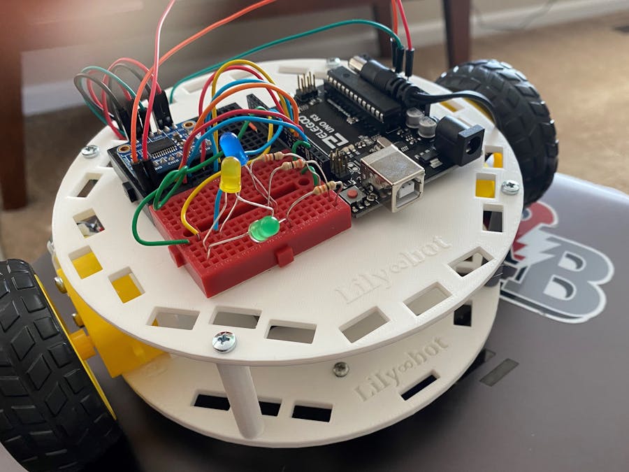
Step 3Use the screws to attach the breadboard and Arduino Uno to the top chassis based upon the following image and labels on chassis. Power port on Uno points towards words.
Top chassis with microcontroller and 2 mini breadboards
Use screws to attach 2 motors to two motor mounts. Then attach wheels to each motor mount as shown in the following image.
1 / 2 • Wheel and motor attached to motor mount and inserted in bottom chassis
Use the screws to attach the motors and wheels to bottom chassis as shown in the image. The robot is now completely built.
1 / 2 • bottom chassis 2ith 2 motors, 2 wheels, battery pack with 4 AA batteries
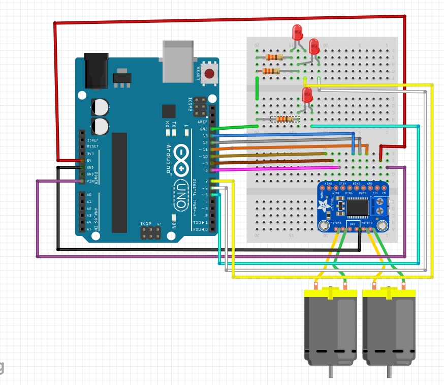
Use the following figure to attach the 3 LEDS, 3 resistors and motor controller to the breadboard. Use the following wiring diagram to connect the motors, LEDs and motor controller to the Arduino Uno.
- Arduino pin 5 Blue LED
- Arduino pin 6 Yellow LED
- Arduino pin 7 Green LED
- Arduino pin 8 AIN1
- Arduino pin 9 AIN2
- Arduino pin 10 PWMA
- Arduino pin 11 PWMB
- Arduino pin 12 BIN2
- Arduino pin 13 BIN1
- Arduino GND GND
- Arduino 5V Vcc
- Arduino VIN Vm
- Left Motor Motor A
- Right Motor Motor B
Step 7Use the code on the GITHub and here to test that the robot is working, it should look like the robot movement in the video.
If you have never programmed in Arduino sketch, please review the link to learn how to program using the cloud editor or IDE.
In order to become more comfortable in programming in Arduino Sketch, start with graphical programming from Code Kit at the following link.
The following Arduino sketch code was generated by graphical programming in Code kit.
Motion Control Using Code Kit
The following Arduino sketch code is generated by Code Kit.
int ylwLED, bluLED, redLED, grnLED, AIN1, AIN2, BIN1, PWMA, BIN2, PWMB;

// move robot forward function
void move_forward2() {
  All_LEDS_ON2();
  digitalWrite(AIN1, HIGH);
  digitalWrite(AIN2, LOW);
  analogWrite(PWMA, 255);
  digitalWrite(BIN1, HIGH);
  digitalWrite(BIN2, LOW);
  analogWrite(PWMB, 255);
}

// turn LEDS off function
void all_LEDS_OFF2() {
  digitalWrite(bluLED, LOW);
  digitalWrite(grnLED, LOW);
  digitalWrite(ylwLED, LOW);
  digitalWrite(redLED, LOW);
}

// all LEDS ON
void All_LEDS_ON2() {
  digitalWrite(bluLED, HIGH);
  digitalWrite(grnLED, HIGH);
  digitalWrite(ylwLED, HIGH);
  digitalWrite(redLED, HIGH);
}

// stop robot function
void stop2() {
  all_LEDS_OFF2();
  digitalWrite(AIN1, LOW);
  digitalWrite(AIN2, LOW);
  digitalWrite(BIN1, LOW);
  digitalWrite(BIN2, LOW);
}

void setup() {
  ylwLED = 10;
  redLED = 11;
  bluLED = 12;
  grnLED = 13;
  AIN1 = 3;
  AIN2 = 4;
  PWMA = 5;
  PWMB = 6;
  BIN1 = 7;
  BIN2 = 8;
  pinMode(AIN1, OUTPUT);
  pinMode(AIN2, OUTPUT);
  pinMode(PWMA, OUTPUT);
  pinMode(BIN1, OUTPUT);
  pinMode(BIN2, OUTPUT);
  pinMode(PWMB, OUTPUT);
  pinMode(bluLED, OUTPUT);
  pinMode(grnLED, OUTPUT);
  pinMode(ylwLED, OUTPUT);
  pinMode(redLED, OUTPUT);
}

void loop() {
  move_forward2();
  delay(1000);
  stop2();
  delay(1000);
}
- Stay tuned and come back for future projects as we expand on the base platform and add more sensors, peripherals and robot behaviors.


_ztBMuBhMHo.jpg?auto=compress%2Cformat&w=48&h=48&fit=fill&bg=ffffff)


Comments