


Hardware components | ||||||
_ztBMuBhMHo.jpg?auto=compress%2Cformat&w=48&h=48&fit=fill&bg=ffffff) |
| × | 1 | |||
Software apps and online services | ||||||
 |
| |||||
Hand tools and fabrication machines | ||||||
 |
| |||||
 |
| |||||
This project is an extension of the Lily∞Bot motion control project. It will show how to add sonar sensors, write code to test sonar sensors and use sonar for potential field obstacle avoidance on the robot.
I am an open-source hardware trailblazer and this is part of my guidebook to show academics how to engage in open source hardware for education, service, and research by using open-source robots.
- Professional website:
- https://wordpress.rose-hulman.edu/berry123/open-source-hardware-trailblazer/
- Business website:
- https://noiresteminist.com/
- YouTube playlist on channel:
- https://youtube.com/playlist?list=PL175eO9NwPXJm3xZPF113ve4L6tO8ckNi
- Instructables:
- https://www.instructables.com/member/carlottaberry/settings/?cb=1658526069
- Hackster.io:
- https://www.hackster.io/berry123
Build the Lily∞Bot by following the project at this link.
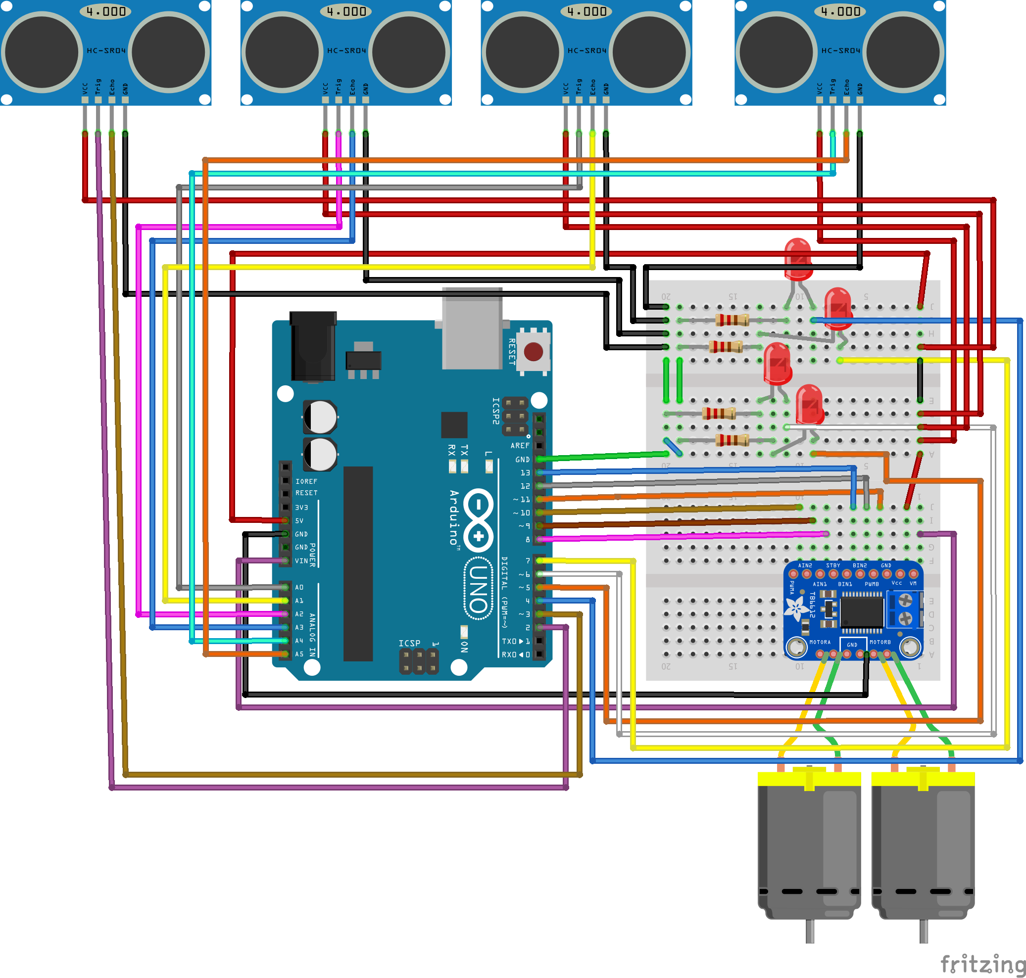
Step 2 - Acquire these supplies- One LED
- One 220Ω resistor
- 4 HC-SR04 sonar
- HC-SR04 sonar mounts 3d printed from files on GITHUB at this link
- 16 male-female wires
- 3 male-female wires
- Put the LED in series with the 220Ω resistor on the breadboard
- Attach the other end of the resistor go ground buss on the breadboard
- Use a wire to attach the other side of the LED to digital pin 4 on the breadboad
- Attach each sonar sensor to one of the mounts
- Attach a mount with sonar to the front, back, left, and right on the robot.
- Use male-female wires to connect the VCC pins to 5V buss on breadboard from Arduino 5V
- Use male-female wires to connect the GND pins to gnd buss on breadboad from Arduino ground
- Connect front sonar trigger pin to digital pin 2 on Arduino
- Connect back sonar trigger pin to analog pin A2 on Arduino
- Connect left sonar trigger pin to analog pin A0 on Arduino
- Connect right sonar trigger pin to analog pin A4 on Arduino
- Connect front sonar echo pin to digital pin 3 on Arduino
- Connect back sonar echo pin to analog pin A3 on Arduino
- Connect left sonar echo pin to analog pin A1 on Arduino
- Connect right sonar echo pin to analog pin A5 on Arduino
- See the wiring diagram in the following figure.
- See the wiring video.
Step 4 - Write Code to Test Sensors (Graphical and Arduino Sketch)
If you have never programmed in Arduino sketch, please review the link to learn how to program using the cloud editor or IDE.
- Use code kit at the following link to use graphical programming to test that each sensor is working.
- The code generated by the graphical program to run in the Arduino IDE is shown below.
- View the video for more details on how the program works.
- Note that the sample code only tests the sensor at A0.
int ylwLED, redLED, trig, bluLED, grnLED, echo;
float dist, echotime;

// read sonar and return distance

int get_distance2() {
  digitalWrite(trig, HIGH);
  delayMicroseconds(10);
  digitalWrite(trig, LOW);
  echotime = pulseInLong(echo, HIGH);
  dist = echotime / 148;
  return dist;
}

// turn of all LEDs
void all_LEDS_off2() {
  digitalWrite(bluLED, LOW);
  digitalWrite(grnLED, LOW);
  digitalWrite(redLED, LOW);
  digitalWrite(ylwLED, LOW);
}

void setup() {
  pinMode(ylwLED, OUTPUT);
  pinMode(redLED, OUTPUT);
  pinMode(bluLED, OUTPUT);
  pinMode(grnLED, OUTPUT);
  ylwLED = 10;
  redLED = 11;
  bluLED = 12;
  grnLED = 13;
  echo = 18;
  trig = 19;
  pinMode(trig, OUTPUT);
}

void loop() {
  if ((get_distance2()) < 4) {
    digitalWrite(ylwLED, HIGH);
  } else if ((get_distance2()) < 7) {
    digitalWrite(redLED, HIGH);
  } else if ((get_distance2()) < 10) {
    digitalWrite(bluLED, HIGH);
  } else {
    digitalWrite(grnLED, HIGH);
  }
  delay(500);
  all_LEDS_off2();
}Watch the video and write the code below.
/*
  Lily∞Bot
  LilyBot-SonarSensors.ino
  Control 2 DC motors with TB6612 motor controller (https://www.adafruit.com/product/2448)
  This program will create low level motion control: forward, reverse, spin, turn, pivot, stop
  with 4 sonar sensors to test that all four are working.

  Carlotta A. Berry, PhD
  August 8, 2022

  Hardware Connections:
  Vmotor - voltage for the motors, not logic level (4.5-13.5V)
  Vcc - voltage for the logic levels (Arduinos, 5V)
  GND - shared logic and motor ground

  INA1, INA2 - two inputs to the Motor A H-bridges
  PWMA - PWM input for the Motor A H-bridges, if you dont need PWM control, connect this to logic high.
  INB1, INB2 - two inputs to the Motor B H-bridges
  PWMB - PWM input for the Motor B H-bridges, if you dont need PWM control, connect this to logic high.
  STBY - standby pin for quickly disabling both motors, pulled up to Vcc thru a 10K resistor. Connect to ground to disable.

  These are 'Vmotor level' power outputs
  Motor A - these are the two outputs for motor A, controlled by INA1, INA2 and PWMA
  Motor B - these are the two outputs for motor B, controlled by INB1, INB2 and PWMB

  Vmotor to VIN
  Vcc to 5V
  GND to ground
  AIN1 to Digital 4
  AIN2 to Digital 5
  BIN1 to Digital 6
  BIN2 to Digital 7
  PWMA and PWMB to Vcc
*/

//state LEDs
int ledPins[3] = {5, 6, 7};
int redLED = 5;
int bluLED = 6;
int grnLED = 7;

//sonar variables
int trigPins[4] = {2, A0, A2, A4};
int echoPins[4] = {3, A1, A3, A5};
int state  = 0b0;
const int trigPin = 2;
const int echoPin = 3;
float distance = 0;            //variable to store the distance measured by the distance sensor
float dist[4];


//the left motor will be controlled by the motor A pins on the motor driver
const int AIN1 = 8;           //control pin 1 on the motor driver for the left motor
const int AIN2 = 9;            //control pin 2 on the motor driver for the left motor
const int PWMA = 10;            //speed control pin on the motor driver for the left motor

//the right motor will be controlled by the motor B pins on the motor driver
const int PWMB = 11;           //speed control pin on the motor driver for the right motor
const int BIN2 = 12;           //control pin 2 on the motor driver for the right motor
const int BIN1 = 13;           //control pin 1 on the motor driver for the right motor

//robot behaviour variables
int moveTime = 200;            //amount of time robot will move
int robotSpeed = 100;           //robot speed

/********************************************************************************/
void setup()
{
  pinMode(trigPin, OUTPUT);       //this pin will send ultrasonic pulses out from the distance sensor
  pinMode(echoPin, INPUT);        //this pin will sense when the pulses reflect back to the distance sensor

  for (int i = 0; i < 3 ; i++) {
    pinMode(ledPins[i], OUTPUT);
  }
  for (int i = 0; i < 4 ; i++) {
    pinMode(trigPins[i], OUTPUT);
  }
  for (int i = 0; i < 4 ; i++) {
    pinMode(echoPins[i], INPUT);
  }
  //for (int i = 0; i < 3 ; i++) {
  //  digitalWrite(ledPins[i], HIGH);
  //}
  //set the motor control pins as outputs
  pinMode(AIN1, OUTPUT);
  pinMode(AIN2, OUTPUT);
  pinMode(PWMA, OUTPUT);

  pinMode(BIN1, OUTPUT);
  pinMode(BIN2, OUTPUT);
  pinMode(PWMB, OUTPUT);

  int baudrate = 9600;              //serial communication baud rate
  Serial.begin(baudrate);           //start serial commnication
  Serial.print("Lily∞bot begin");  //print start message
  int waittime = 5000;               //robot wait time
  delay(waittime);                  //robot delay before moving
  allLedsOff();
}

/********************************************************************************/
void loop()
{
  distance = getDistance();
  Serial.print("Distance: ");
  Serial.print(distance);
  Serial.println(" in");              // print the units
  if (distance < 5) {
    Serial.print("obstacle\n");
    allLedsOff();
    stop();
    delay(moveTime);
    rev(robotSpeed);
    delay(4 * moveTime);
    spin(robotSpeed, 1);
    delay(8 * moveTime);
  } else {
    Serial.print("forward");
    fwd(robotSpeed);
    delay(moveTime);
  }

}

//robot stop function
void stop() {
  allLedsOff();
  digitalWrite(redLED, HIGH);
  //left motor stop
  digitalWrite(AIN1, LOW);                          //set pin 1 to low
  digitalWrite(AIN2, LOW);                          //set pin 2 to low
  //right motor stop
  digitalWrite(BIN1, LOW);                          //set pin 1 to low
  digitalWrite(BIN2, LOW);                          //set pin 2 to low
}

//robot forward function
void fwd(int speed) {
  allLedsOff();
  digitalWrite(grnLED, HIGH);
  digitalWrite(AIN1, HIGH);                         //set pin 1 to high
  digitalWrite(AIN2, LOW);                          //set pin 2 to low
  digitalWrite(BIN1, HIGH);                         //set pin 1 to low
  digitalWrite(BIN2, LOW);                        //set pin 2 to high
  analogWrite(PWMA, abs(speed));    //set forward speed
  analogWrite(PWMB, abs(speed));    //set forward speed
}

//robot reverse function
void rev(int speed) {
  allLedsOff();
  digitalWrite(bluLED, HIGH);
  digitalWrite(AIN1, LOW);                         //set pin 1 to low
  digitalWrite(AIN2, HIGH);                        //set pin 2 to high
  digitalWrite(BIN1, LOW);                         //set pin 1 to low
  digitalWrite(BIN2, HIGH);                        //set pin 2 to high
  analogWrite(PWMA, abs(speed));    //set reverse speed
  analogWrite(PWMB, abs(speed));    //set reverse speed
}

//robot spin function
void spin(int speed, int dir) {
  //digitalWrite(grnLED, HIGH);
  if (dir > 0) {
    digitalWrite(AIN1, LOW);                         //set pin 1 to low
    digitalWrite(AIN2, HIGH);                        //set pin 2 to high
    digitalWrite(BIN1, HIGH);                         //set pin 1 to low
    digitalWrite(BIN2, LOW);                        //set pin 2 to high
  } else {
    digitalWrite(AIN1, HIGH);                         //set pin 1 to low
    digitalWrite(AIN2, LOW);                        //set pin 2 to high
    digitalWrite(BIN1, LOW);                         //set pin 1 to low
    digitalWrite(BIN2, HIGH);                        //set pin 2 to high
  }
  analogWrite(PWMA, abs(speed));    //set reverse speed
  analogWrite(PWMB, abs(speed));    //set reverse speed
}

//robot turn function
void turn(int speed, int dir) {
  //digitalWrite(redLED, HIGH);
  //digitalWrite(bluLED, HIGH);
  digitalWrite(AIN1, HIGH);                         //set pin 1 to low
  digitalWrite(AIN2, LOW);                        //set pin 2 to high
  digitalWrite(BIN1, HIGH);                         //set pin 1 to low
  digitalWrite(BIN2, LOW);                        //set pin 2 to high
  if (dir > 0) {
    analogWrite(PWMA, robotSpeed * 1.5);
    analogWrite(PWMB, robotSpeed * 0.5);
  }
  else {
    analogWrite(PWMA, robotSpeed * 0.5);
    analogWrite(PWMB, robotSpeed * 1.5);
  }
}

//robot pivot function
void pivot(int speed, int dir) {
  //digitalWrite(bluLED, HIGH);
  //digitalWrite(grnLED, HIGH);
  digitalWrite(AIN1, HIGH);                         //set pin 1 to low
  digitalWrite(AIN2, LOW);                        //set pin 2 to high
  digitalWrite(BIN1, HIGH);                         //set pin 1 to low
  digitalWrite(BIN2, LOW);                        //set pin 2 to high
  if (dir > 0) {
    analogWrite(PWMA, 0);
    analogWrite(PWMB, abs(speed));
  }
  else {
    analogWrite(PWMA, abs(speed));
    analogWrite(PWMB, 0);
  }
}

//turn all the LEDS off
void allLedsOff () {
  for (int i = 0; i < 3 ; i++) {
    digitalWrite(ledPins[i], LOW);
  }
}

//get sonar distance
float getDistance()
{
  float echoTime;                   //variable to store the time it takes for a ping to bounce off an object
  float calculatedDistance;         //variable to store the distance calculated from the echo time

  //send out an ultrasonic pulse that's 10ms long
  digitalWrite(trigPin, HIGH);
  delayMicroseconds(10);
  digitalWrite(trigPin, LOW);

  echoTime = pulseIn(echoPin, HIGH);      //use the pulsein command to see how long it takes for the
  //pulse to bounce back to the sensor

  calculatedDistance = echoTime / 148.0;  //calculate the distance of the object that reflected the pulse (half the bounce time multiplied by the speed of sound)

  return calculatedDistance;              //send back the distance that was calculated
}
Watch the video and write the following code to implement bang-bang control obstacle avoidance on the robot.
/*
  Lily∞Bot
  LilyBot-SonarSensors.ino
  Control 2 DC motors with TB6612 motor controller (https://www.adafruit.com/product/2448)
  This program will create low level motion control: forward, reverse, spin, turn, pivot, stop
  with 4 sonar sensors to test that all four are working.

  Carlotta A. Berry, PhD
  August 8, 2022

  Hardware Connections:
  Vmotor - voltage for the motors, not logic level (4.5-13.5V)
  Vcc - voltage for the logic levels (Arduinos, 5V)
  GND - shared logic and motor ground

  INA1, INA2 - two inputs to the Motor A H-bridges
  PWMA - PWM input for the Motor A H-bridges, if you dont need PWM control, connect this to logic high.
  INB1, INB2 - two inputs to the Motor B H-bridges
  PWMB - PWM input for the Motor B H-bridges, if you dont need PWM control, connect this to logic high.
  STBY - standby pin for quickly disabling both motors, pulled up to Vcc thru a 10K resistor. Connect to ground to disable.

  These are 'Vmotor level' power outputs
  Motor A - these are the two outputs for motor A, controlled by INA1, INA2 and PWMA
  Motor B - these are the two outputs for motor B, controlled by INB1, INB2 and PWMB

  Vmotor to VIN
  Vcc to 5V
  GND to ground
  AIN1 to Digital 4
  AIN2 to Digital 5
  BIN1 to Digital 6
  BIN2 to Digital 7
  PWMA and PWMB to Vcc
*/

//state LEDs
int ledPins[3] = {5, 6, 7};
int redLED = 5;
int bluLED = 6;
int grnLED = 7;

//sonar variables
int trigPins[4] = {2, A0, A2, A4};
int echoPins[4] = {3, A1, A3, A5};
int state  = 0b0;
const int trigPin = 2;
const int echoPin = 3;
float distance = 0;            //variable to store the distance measured by the distance sensor
float dist[4];


//the left motor will be controlled by the motor A pins on the motor driver
const int AIN1 = 8;           //control pin 1 on the motor driver for the left motor
const int AIN2 = 9;            //control pin 2 on the motor driver for the left motor
const int PWMA = 10;            //speed control pin on the motor driver for the left motor

//the right motor will be controlled by the motor B pins on the motor driver
const int PWMB = 11;           //speed control pin on the motor driver for the right motor
const int BIN2 = 12;           //control pin 2 on the motor driver for the right motor
const int BIN1 = 13;           //control pin 1 on the motor driver for the right motor

//robot behaviour variables
int moveTime = 200;            //amount of time robot will move
int robotSpeed = 100;           //robot speed

/********************************************************************************/
void setup()
{
  pinMode(trigPin, OUTPUT);       //this pin will send ultrasonic pulses out from the distance sensor
  pinMode(echoPin, INPUT);        //this pin will sense when the pulses reflect back to the distance sensor

  for (int i = 0; i < 3 ; i++) {
    pinMode(ledPins[i], OUTPUT);
  }
  for (int i = 0; i < 4 ; i++) {
    pinMode(trigPins[i], OUTPUT);
  }
  for (int i = 0; i < 4 ; i++) {
    pinMode(echoPins[i], INPUT);
  }
  //for (int i = 0; i < 3 ; i++) {
  //  digitalWrite(ledPins[i], HIGH);
  //}
  //set the motor control pins as outputs
  pinMode(AIN1, OUTPUT);
  pinMode(AIN2, OUTPUT);
  pinMode(PWMA, OUTPUT);

  pinMode(BIN1, OUTPUT);
  pinMode(BIN2, OUTPUT);
  pinMode(PWMB, OUTPUT);

  int baudrate = 9600;              //serial communication baud rate
  Serial.begin(baudrate);           //start serial commnication
  Serial.print("Lily∞bot begin");  //print start message
  int waittime = 5000;               //robot wait time
  delay(waittime);                  //robot delay before moving
  allLedsOff();
}

/********************************************************************************/
void loop()
{
  distance = getDistance();
  Serial.print("Distance: ");
  Serial.print(distance);
  Serial.println(" in");              // print the units
  if (distance < 5) {
    Serial.print("obstacle\n");
    allLedsOff();
    stop();
    delay(moveTime);
    rev(robotSpeed);
    delay(4 * moveTime);
    spin(robotSpeed, 1);
    delay(8 * moveTime);
  } else {
    Serial.print("forward");
    fwd(robotSpeed);
    delay(moveTime);
  }

}

//robot stop function
void stop() {
  allLedsOff();
  digitalWrite(redLED, HIGH);
  //left motor stop
  digitalWrite(AIN1, LOW);                          //set pin 1 to low
  digitalWrite(AIN2, LOW);                          //set pin 2 to low
  //right motor stop
  digitalWrite(BIN1, LOW);                          //set pin 1 to low
  digitalWrite(BIN2, LOW);                          //set pin 2 to low
}

//robot forward function
void fwd(int speed) {
  allLedsOff();
  digitalWrite(grnLED, HIGH);
  digitalWrite(AIN1, HIGH);                         //set pin 1 to high
  digitalWrite(AIN2, LOW);                          //set pin 2 to low
  digitalWrite(BIN1, HIGH);                         //set pin 1 to low
  digitalWrite(BIN2, LOW);                        //set pin 2 to high
  analogWrite(PWMA, abs(speed));    //set forward speed
  analogWrite(PWMB, abs(speed));    //set forward speed
}

//robot reverse function
void rev(int speed) {
  allLedsOff();
  digitalWrite(bluLED, HIGH);
  digitalWrite(AIN1, LOW);                         //set pin 1 to low
  digitalWrite(AIN2, HIGH);                        //set pin 2 to high
  digitalWrite(BIN1, LOW);                         //set pin 1 to low
  digitalWrite(BIN2, HIGH);                        //set pin 2 to high
  analogWrite(PWMA, abs(speed));    //set reverse speed
  analogWrite(PWMB, abs(speed));    //set reverse speed
}

//robot spin function
void spin(int speed, int dir) {
  //digitalWrite(grnLED, HIGH);
  if (dir > 0) {
    digitalWrite(AIN1, LOW);                         //set pin 1 to low
    digitalWrite(AIN2, HIGH);                        //set pin 2 to high
    digitalWrite(BIN1, HIGH);                         //set pin 1 to low
    digitalWrite(BIN2, LOW);                        //set pin 2 to high
  } else {
    digitalWrite(AIN1, HIGH);                         //set pin 1 to low
    digitalWrite(AIN2, LOW);                        //set pin 2 to high
    digitalWrite(BIN1, LOW);                         //set pin 1 to low
    digitalWrite(BIN2, HIGH);                        //set pin 2 to high
  }
  analogWrite(PWMA, abs(speed));    //set reverse speed
  analogWrite(PWMB, abs(speed));    //set reverse speed
}

//robot turn function
void turn(int speed, int dir) {
  //digitalWrite(redLED, HIGH);
  //digitalWrite(bluLED, HIGH);
  digitalWrite(AIN1, HIGH);                         //set pin 1 to low
  digitalWrite(AIN2, LOW);                        //set pin 2 to high
  digitalWrite(BIN1, HIGH);                         //set pin 1 to low
  digitalWrite(BIN2, LOW);                        //set pin 2 to high
  if (dir > 0) {
    analogWrite(PWMA, robotSpeed * 1.5);
    analogWrite(PWMB, robotSpeed * 0.5);
  }
  else {
    analogWrite(PWMA, robotSpeed * 0.5);
    analogWrite(PWMB, robotSpeed * 1.5);
  }
}

//robot pivot function
void pivot(int speed, int dir) {
  //digitalWrite(bluLED, HIGH);
  //digitalWrite(grnLED, HIGH);
  digitalWrite(AIN1, HIGH);                         //set pin 1 to low
  digitalWrite(AIN2, LOW);                        //set pin 2 to high
  digitalWrite(BIN1, HIGH);                         //set pin 1 to low
  digitalWrite(BIN2, LOW);                        //set pin 2 to high
  if (dir > 0) {
    analogWrite(PWMA, 0);
    analogWrite(PWMB, abs(speed));
  }
  else {
    analogWrite(PWMA, abs(speed));
    analogWrite(PWMB, 0);
  }
}

//turn all the LEDS off
void allLedsOff () {
  for (int i = 0; i < 3 ; i++) {
    digitalWrite(ledPins[i], LOW);
  }
}

//get sonar distance
float getDistance()
{
  float echoTime;                   //variable to store the time it takes for a ping to bounce off an object
  float calculatedDistance;         //variable to store the distance calculated from the echo time

  //send out an ultrasonic pulse that's 10ms long
  digitalWrite(trigPin, HIGH);
  delayMicroseconds(10);
  digitalWrite(trigPin, LOW);

  echoTime = pulseIn(echoPin, HIGH);      //use the pulsein command to see how long it takes for the
  //pulse to bounce back to the sensor

  calculatedDistance = echoTime / 148.0;  //calculate the distance of the object that reflected the pulse (half the bounce time multiplied by the speed of sound)

  return calculatedDistance;              //send back the distance that was calculated
}Step 7 - Proportional Control with Speed Obstacle Avoidance
Watch the video and write the following code to implement bang-bang control obstacle avoidance on the robot.
/*
  //Lily∞Bot
  LilyBot-Avoid-Speed.ino
  Control 2 DC motors with TB6612 motor controller (https://www.adafruit.com/product/2448)
  This program will create low level motion control: forward, reverse, spin, turn, pivot, stop
  It will then use proportional feedback control with sonar sensors to create obstacle avoidance

  Carlotta A. Berry, PhD
  August 8, 2022

  Hardware Connections:
  Vmotor - voltage for the motors, not logic level (4.5-13.5V)
  Vcc - voltage for the logic levels (Arduinos, 5V)
  GND - shared logic and motor ground

  INA1, INA2 - two inputs to the Motor A H-bridges
  PWMA - PWM input for the Motor A H-bridges, if you dont need PWM control, connect this to logic high.
  INB1, INB2 - two inputs to the Motor B H-bridges
  PWMB - PWM input for the Motor B H-bridges, if you dont need PWM control, connect this to logic high.
  STBY - standby pin for quickly disabling both motors, pulled up to Vcc thru a 10K resistor. Connect to ground to disable.

  These are 'Vmotor level' power outputs
  Motor A - these are the two outputs for motor A, controlled by INA1, INA2 and PWMA
  Motor B - these are the two outputs for motor B, controlled by INB1, INB2 and PWMB

  Vmotor to VIN
  Vcc to 5V
  GND to ground
  AIN1 to Digital 8
  AIN2 to Digital 9
  BIN1 to Digital 13
  BIN2 to Digital 12
  PWMA to Digital 10
  PWMB to Digital 11
*/

//state LEDs
int ledPins[4] = {7, 6, 5, 4};
int redLED = 5;     //left LED
int bluLED = 6;     //right LED
int grnLED = 7;     //front LED
int ylwLED = 4;     //back LED

//sonar variables
int trigPins[4] = {2, A2, A0, A4};    //{front,back, left, right}
int echoPins[4] = {3, A3, A1, A5};    //{front,back, left, right}
float dist[4];                          //distance for each sonar
int maxDetect = 5;                          //maximum detect distance to indicate an obstacle

//the left motor will be controlled by the motor A pins on the motor driver
const int AIN1 = 8;           //control pin 1 on the motor driver for the left motor,
const int AIN2 = 9;            //control pin 2 on the motor driver for the left motor
const int PWMA = 10;            //speed control pin on the motor driver for the left motor

//the right motor will be controlled by the motor B pins on the motor driver
const int PWMB = 11;           //speed control pin on the motor driver for the right motor
const int BIN2 = 12;           //control pin 2 on the motor driver for the right motor
const int BIN1 = 13;           //control pin 1 on the motor driver for the right motor

//robot behaviour variables
int maxDist = 200;            //amount of time robot will move
int robotSpeed = 255;           //robot speed
int propSpeed = 0;                  //robot speed proportional to detect distance
int propDist = 0;               //robot moves away proportional to distance to obstacle
int oneSecond = 1000;           //1s delay time variable
int twoSeconds = 2000;          //2s delay time variable
int waittime = 100;           //robot wait time
int state  = 0;                       //robot state variable {front, back, left, right}


/********************************************************************************/


void setup()
{

  for (int i = 0; i < 4 ; i++) {// this declares the LED pins as outputs
    pinMode(ledPins[i], OUTPUT);
  }
  for (int i = 0; i < 4 ; i++) {//this pin will send ultrasonic pulses out from the distance sensor
    pinMode(trigPins[i], OUTPUT);
  }
  for (int i = 0; i < 4 ; i++) {//this pin will sense when the pulses reflect back to the distance sensor
    pinMode(echoPins[i], INPUT);
  }
  for (int i = 0; i < 4 ; i++) {
    digitalWrite(ledPins[i], HIGH);
    delay(waittime);
  }
  // set the motor control pins as outputs
  pinMode(AIN1, OUTPUT);
  pinMode(AIN2, OUTPUT);
  pinMode(PWMA, OUTPUT);

  pinMode(BIN1, OUTPUT);
  pinMode(BIN2, OUTPUT);
  pinMode(PWMB, OUTPUT);

  int baudrate = 9600;              //serial communication baud rate
  Serial.begin(baudrate);           //start serial commnication
  Serial.print("Lily∞bot begin");  //print start message

  delay(waittime);                  //robot delay before moving
  for (int i = 3; i > -1 ; i--) {
    digitalWrite(ledPins[i], LOW);
    delay(waittime);
  }
}

/********************************************************************************/
void loop()
{
  for (int i = 0; i < 4 ; i++) {//this pin will send ultrasonic pulses out from the distance sensor
    dist[i] = getDistance(&trigPins[i], &echoPins[i]);
    delayMicroseconds(10);
    //Serial.print(dist[i]);
    //Serial.print("\t");
    if (dist[i] < maxDetect && dist[i] > 0) {
      bitSet(state, i);
      digitalWrite(ledPins[i], HIGH);
      propDist = maxDist*(1-dist[i]/maxDetect);
      Serial.print("robot distance: ");
      Serial.println(propDist);
      propSpeed = robotSpeed*(1-dist[i]/maxDetect);
      //Serial.print("robot speed: ");
      //Serial.println(propSpeed);
    } else {
      bitClear(state, i);
      digitalWrite(ledPins[i], LOW);
    }
  }
  //Serial.print("\n");
  //Serial.print(" state (fblr) = ");
  //Serial.println(state,BIN);

  switch (state) {
    case 1: //front obstacle
      Serial.println("front obstacles");
      rev(robotSpeed);
      delay(propDist);
      stop();
      break;
    case 2: //back obstacle
      Serial.println("back obstacle");
      fwd(robotSpeed);
      delay(propDist);
      stop();
      break;
    case 4: //left obstacle
      Serial.println("left obstacle");
      spin(robotSpeed, 1); //spin right
            delay(propDist);
      stop();
      break;
    case 8: //right obstacle
      Serial.println("right obstacle");
      spin(robotSpeed, -1); //spin left
      delay(propDist);
      stop();
      break;
    default: //no obstacle
      Serial.println("no obstacles");
      stop();
      break;
  }

  delay(100);//For testing purposes
}Watch the video and write the following code to implement bang-bang control obstacle avoidance on the robot.
 /*
  //Lily∞Bot
  LilyBot-AvoidDistProportional.ino
  Control 2 DC motors with TB6612 motor controller (https://www.adafruit.com/product/2448)
  This program will create low level motion control: forward, reverse, spin, turn, pivot, stop
  It will then implement proportional feedback obstacle avoidance using 4 HC-SR04 ultrasonic distance sensors

  Carlotta A. Berry, PhD
  August 8, 2022

  Hardware Connections:
  Vmotor - voltage for the motors, not logic level (4.5-13.5V)
  Vcc - voltage for the logic levels (Arduinos, 5V)
  GND - shared logic and motor ground

  INA1, INA2 - two inputs to the Motor A H-bridges
  PWMA - PWM input for the Motor A H-bridges, if you dont need PWM control, connect this to logic high.
  INB1, INB2 - two inputs to the Motor B H-bridges
  PWMB - PWM input for the Motor B H-bridges, if you dont need PWM control, connect this to logic high.
  STBY - standby pin for quickly disabling both motors, pulled up to Vcc thru a 10K resistor. Connect to ground to disable.

  These are 'Vmotor level' power outputs
  Motor A - these are the two outputs for motor A, controlled by INA1, INA2 and PWMA
  Motor B - these are the two outputs for motor B, controlled by INB1, INB2 and PWMB

  Vmotor to VIN
  Vcc to 5V
  GND to ground
  AIN1 to Digital 8
  AIN2 to Digital 9
  BIN1 to Digital 13
  BIN2 to Digital 12
  PWMA to Digital 10
  PWMB to Digital 11
*/

//state LEDs
int ledPins[4] = {7, 6, 5, 4};
int redLED = 5;     //left LED
int bluLED = 6;     //right LED
int grnLED = 7;     //front LED
int ylwLED = 4;     //back LED

//sonar variables
int trigPins[4] = {2, A2, A0, A4};    //{front,back, left, right}
int echoPins[4] = {3, A3, A1, A5};    //{front,back, left, right}
float dist[4];                          //distance for each sonar
int maxDetect = 5;                          //maximum detect distance to indicate an obstacle

//the left motor will be controlled by the motor A pins on the motor driver
const int AIN1 = 8;           //control pin 1 on the motor driver for the left motor,
const int AIN2 = 9;            //control pin 2 on the motor driver for the left motor
const int PWMA = 10;            //speed control pin on the motor driver for the left motor

//the right motor will be controlled by the motor B pins on the motor driver
const int PWMB = 11;           //speed control pin on the motor driver for the right motor
const int BIN2 = 12;           //control pin 2 on the motor driver for the right motor
const int BIN1 = 13;           //control pin 1 on the motor driver for the right motor

//robot behaviour variables
int moveTime = 200;            //amount of time robot will move
int robotSpeed = 255;           //robot speed
int propSpeed = 0;                  //robot speed proportional to detect distance
int oneSecond = 1000;           //1s delay time variable
int twoSeconds = 2000;          //2s delay time variable
int waittime = 100;           //robot wait time
int state  = 0;                       //robot state variable {front, back, left, right}


/********************************************************************************/


void setup()
{

  for (int i = 0; i < 4 ; i++) {// this declares the LED pins as outputs
    pinMode(ledPins[i], OUTPUT);
  }
  for (int i = 0; i < 4 ; i++) {//this pin will send ultrasonic pulses out from the distance sensor
    pinMode(trigPins[i], OUTPUT);
  }
  for (int i = 0; i < 4 ; i++) {//this pin will sense when the pulses reflect back to the distance sensor
    pinMode(echoPins[i], INPUT);
  }
  for (int i = 0; i < 4 ; i++) {
    digitalWrite(ledPins[i], HIGH);
    delay(waittime);
  }
  // set the motor control pins as outputs
  pinMode(AIN1, OUTPUT);
  pinMode(AIN2, OUTPUT);
  pinMode(PWMA, OUTPUT);

  pinMode(BIN1, OUTPUT);
  pinMode(BIN2, OUTPUT);
  pinMode(PWMB, OUTPUT);

  int baudrate = 9600;              //serial communication baud rate
  Serial.begin(baudrate);           //start serial commnication
  Serial.print("Lily∞bot begin");  //print start message

  delay(waittime);                  //robot delay before moving
  for (int i = 3; i > -1 ; i--) {
    digitalWrite(ledPins[i], LOW);
    delay(waittime);
  }
}

/********************************************************************************/
void loop()
{
  for (int i = 0; i < 4 ; i++) {//this pin will send ultrasonic pulses out from the distance sensor
    dist[i] = getDistance(&trigPins[i], &echoPins[i]);
    delayMicroseconds(10);
    //Serial.print(dist[i]);
    //Serial.print("\t");
    if (dist[i] < maxDetect && dist[i] > 0) {
      bitSet(state, i);
      digitalWrite(ledPins[i], HIGH);
      propSpeed = robotSpeed*(1-dist[i]/maxDetect);
      Serial.print("robot speed: ");
      Serial.println(propSpeed);
    } else {
      bitClear(state, i);
      digitalWrite(ledPins[i], LOW);
    }
  }
  //Serial.print("\n");
  //Serial.print(" state (fblr) = ");
  //Serial.println(state,BIN);

  switch (state) {
    case 1: //front obstacle
      Serial.println("front obstacles");
      rev(propSpeed);
      break;
    case 2: //back obstacle
      Serial.println("back obstacle");
      fwd(propSpeed);
      break;
    case 4: //left obstacle
      Serial.println("left obstacle");
      spin(propSpeed, 1); //spin right
      break;
    case 8: //right obstacle
      Serial.println("right obstacle");
      spin(propSpeed, -1); //spin left
      break;
    default: //no obstacle
      Serial.println("no obstacles");
      stop();
      break;
  }

  delay(100);//For testing purposes
}


Comments