


Hardware components | ||||||
 |
| × | 1 | |||
Software apps and online services | ||||||
 |
| |||||
Storytelling:
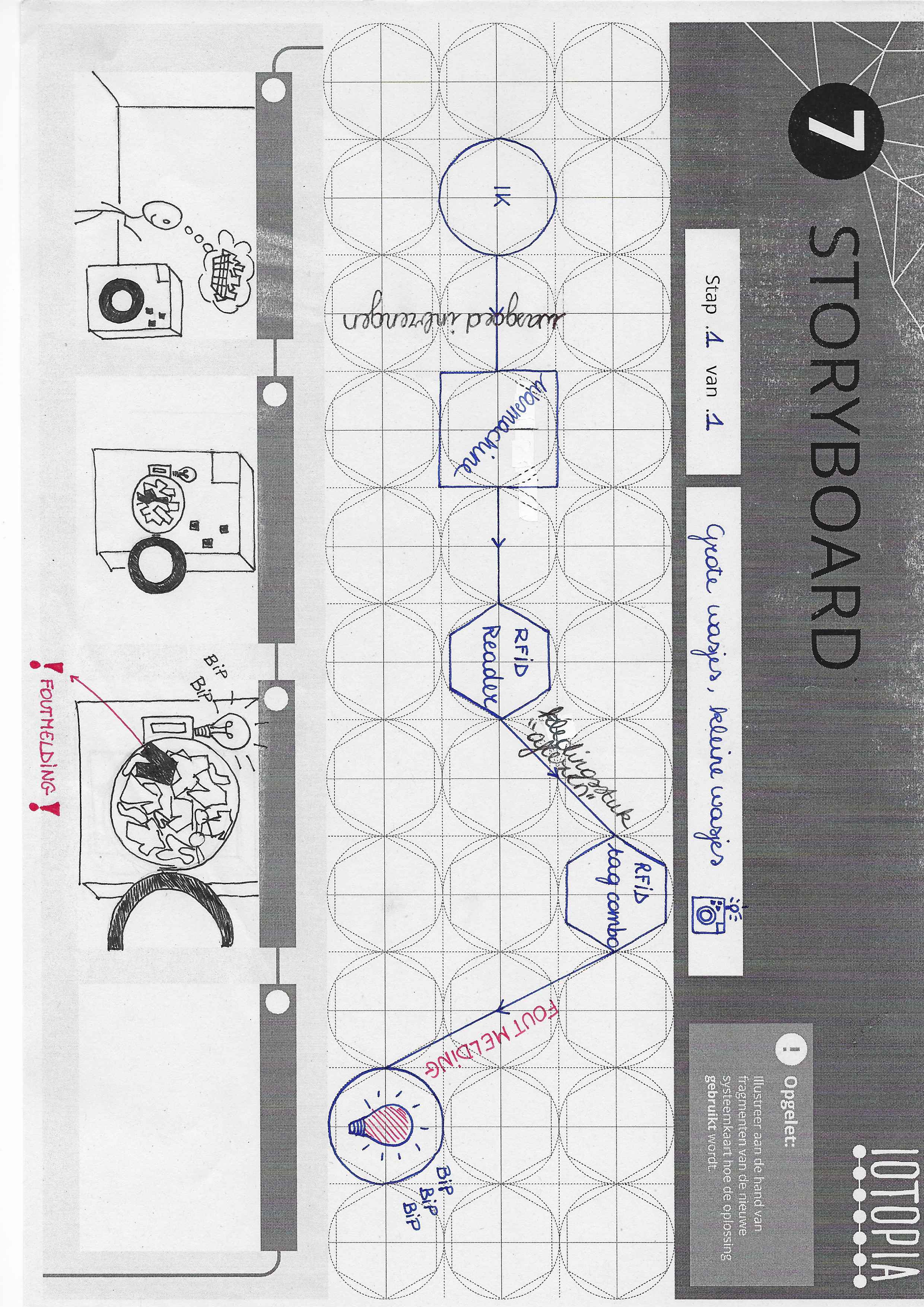
Our idea was made in an attempt to create a device to ensure the complete lack of wrong clothes in your laundry. We imagined to realize this by supplying all of your clothes with a small chip holding data about color, and clothtype. By scanning these items each time they cross the door of the machine we can throw a warning when a wrong item is inserted together with a lightblink and a noise.
Ideation:
This was invented as we all had to throw away an entire machine load of clothes because of one rogue red sock coloring everything pink multiple times in the past. This could also find use in certain situations where people have difficulties differentiating certain colours.
Video:
Foto's:
Main
ArduinoMain file for this project, in here data gets processed and an output gets formed.
due to technical issues it is yet untested.
due to technical issues it is yet untested.
#include <ATT_IOT_UART.h>
#include <SerialCommands.h>
#include "pitches.h"
/*
  SmartLiving Makers Arduino UART Demo Sketch
  version 1.0 dd 25/11/2015

  This file is an example sketch to deploy a digital sensor and actuator in the SmartLiving.io IoT platform.

  ### Instructions

  1. Setup the Arduino hardware
    - Use an Arduino Genuino 101 IoT board
    - Connect the Arduino Grove shield
    - Connect USB cable to your computer
    - Connect a Grove push button to Pin D8 of the Grove shield
    - Connect a LED to Pin D7
    - Connect Grove wifi to pin UART (D0,D1)

  2. Add 'ATT_IOT_UART' library to your Arduino Environment. [Try this guide](http://arduino.cc/en/Guide/Libraries)
  3. Fill in the missing strings (deviceId, clientId, clientKey) and optionally change/add the sensor & actuator names, ids, descriptions, types
     For extra actuators, make certain to extend the callback code at the end of the sketch.
  4. Upload the sketch

  Note: for use of extra actuators, extend the callback function at the end of the sketch

*/

#include "ATT_IOT_UART.h"         // AllThingsTalk IoT library
#include <SPI.h>                  // Required to have support for signed/unsigned long type.
#include "keys.h"                 // Keep all your personal account information in a seperate file
#include <SoftwareSerial.h>
SoftwareSerial RFID(2, 3); // RX and TX

 int data1 = 0;
int ok = -1;
int yes = 13;
int no = 12;
int i;

int melody[] = {                    //toon die gespeeld wordt bij foutieve invoer
  NOTE_C4, NOTE_G3, NOTE_G3, NOTE_A3, NOTE_G3, 0, NOTE_B3, NOTE_C4
};


// use first sketch in http://wp.me/p3LK05-3Gk to get your tag numbers, could not be done due to technical malfunctions. Data below needs to be adjusted to match your tags
int tag1[14] = {2,52,48,48,48,56,54,66,49,52,70,51,56,3};
int tag2[14] = {2,52,48,48,48,56,54,67,54,54,66,54,66,3};
int newtag[14] = { 0,0,0,0,0,0,0,0,0,0,0,0,0,0}; // used for read comparisons

// Enter below your client credentials.
// These credentials can be found in the configuration pane under your device in the smartliving.io website

ATTDevice Device(&Serial1);
char httpServer[] = "api.smartliving.io";                       // HTTP API Server host
char mqttServer[] = "broker.smartliving.io";                    // MQTT Server Address


// Define PIN numbers for assets
// For digital and analog sensors, we recommend to use the physical pin id as the asset id
// For other sensors (I2C and UART), you can select any unique number as the asset id
#define DigitalSensor 8                                         // Digital Sensor is connected to pin D8 on grove shield
#define DigitalActuator 7
//#define DigitalRFID 9

// Required for the device
void callback(int pin, String& value);


void setup()
{
  pinMode(7, OUTPUT);
  pinMode(DigitalSensor, INPUT);                                // Initialize the digital pin as an input.
  pinMode(DigitalActuator, OUTPUT);                             // Initialize the digital pin as an output.
  Serial.begin(57600);                                          // Init serial link for debugging
  while(!Serial);
  Serial.println("Starting sketch");
  Serial1.begin(115200);                                        // Init software serial link for WiFi
  while(!Serial1);

  pinMode(yes, OUTPUT); // for status LEDs
  pinMode(no, OUTPUT);

  while(!Device.StartWifi())
    Serial.println("retrying...");
  while(!Device.Init(DEVICEID, CLIENTID, CLIENTKEY))            // If we can't succeed to initialize and set the device credentials, there is no point to continue
    Serial.println("retrying...");
  while(!Device.Connect(httpServer))                            // connect the device with the IOT platform. No point to continue if we can't succeed at this
    Serial.println("retrying");

  Device.AddAsset(DigitalSensor, "sensor", "Digital Sensor Description", false, "boolean");     // Create the Digital Sensor asset for your device
  Device.AddAsset(DigitalActuator, "acuator", "Digital Sensor Description", true, "boolean");   // Create the Digital Actuator asset for your device
  //Device.AddAsset(DigitalRFID, "RFID sensor", "Digital Sensor Description", false, "boolean");

  delay(1000);                                                  // Give the WiFi some time to finish everything
  while(!Device.Subscribe(mqttServer, callback))                // Make certain that we can receive message from the IoT platform (MQTT). This stops the http connection
    Serial.println("retrying");

  Device.Send("false", DigitalActuator);
  Serial.println("button is ready");


  }

}

//xxxxxxxxxxxxxxxxxxxxxxxxxxxxxxxxxxxxxxxxxxxxxxxxxxxxxxxxxxxxxxxxxxxxxxxxxxxxxxxxxxxxxxxxxxxxx

boolean comparetag(int aa[14], int bb[14])
{
  boolean ff = false;
  int fg = 0;
  for (int cc = 0 ; cc < 14 ; cc++)
  {
    if (aa[cc] == bb[cc])
    {
      fg++;
    }
  }
  if (fg == 14)
  {
    ff = true;
  }
  return ff;
}

void checkmytags() // compares each tag against the tag just read
{
  ok = 0; // this variable helps decision-making,
  // if it is 1 we have a match, zero is a read but no match,
  // -1 is no read attempt made
  if (comparetag(newtag, tag1) == true)
  {
    ok++;
  }
  if (comparetag(newtag, tag2) == true)
  {
    ok++;
  }
}

void readTags()
{
  ok = -1;

  if (RFID.available() > 0)
  {
    // read tag numbers
    delay(100); // needed to allow time for the data to come in from the serial buffer.

    for (int z = 0 ; z < 14 ; z++) // read the rest of the tag
    {
      data1 = RFID.read();
      newtag[z] = data1;
    }
    RFID.flush(); // stops multiple reads

    // do the tags match up?
    checkmytags();
  }

  // now do something based on tag type
  if (ok > 0) // if we had a match
  {
    Serial.println("Accepted");
    digitalWrite(yes, HIGH);
    delay(1000);
    digitalWrite(yes, LOW);

    ok = -1;
  }
  else if (ok == 0) // if we didn't have a match
  {
    Serial.println("wrong color, remove latest input");
    digitalWrite(no, HIGH);
    delay(1000);
    digitalWrite(no, LOW);

    ok = -1;
  }
  //xxxxxxxxxxxxxxxxxxxxxxxxxxxxxxxxxxxxxxxxxxxxxxxxxxxxxxxxxxxxxxxxxxxxxxxxxxxxxxxxxxxxxxxxxxxxxxxxxxxxxxxxxxxxxxxxxxxxxxxxxxxxxxxxxxxx
}

bool sensorVal = false;
void loop()
{
  //xxxxxxxxxxxxxxxxxxxxxxxxxxxxxxxxxxxxxxxxxxxxxxxxxxxxxxxxxxxxxxxxxxxxxxxxxxxxxxxxxxxxxxxxxxxxxxxxxxxxxxxxxxxxxxxxxxxxxxxxxxxxx
  bool sensorRead = digitalRead(DigitalSensor);                 // Read status Digital Sensor
  if (sensorVal != sensorRead)                                  // Verify if value has changed
  {
    sensorVal = sensorRead;
    if (sensorRead == 1)
      Device.Send("true", DigitalSensor);
    else
      Device.Send("false", DigitalSensor);
  }

 if (RFID.available() > 0)
  {
     i = RFID.read();
     Serial.print(i, DEC);
     Serial.print(" ");
  }
//xxxxxxxxxxxxxxxxxxxxxxxxxxxxxxxxxxxxxxxxxxxxxxxxxxxxxxxxxxxxxxxxxxxxxxxxxxxxxxxxxxxxxxxxxxxxxxxxxxxxxxxxxxxxxxxxxxxxxxxxxxxxxxx
  readTags();//see line131-149

if(ok==-1){                                                                   //blinking leds when wrong attire is inserte in machine
  digitalWrite(13, HIGH);   // turn the LED on (HIGH is the voltage level)
  delay(1000);              // wait for a second
  digitalWrite(13, LOW);    // turn the LED off by making the voltage LOW
  delay(500);

  for (int thisNote = 0; thisNote < 8; thisNote++) {           //creates a tone array to be played

    // to calculate the note duration, take one second
    // divided by the note type.
    //e.g. quarter note = 1000 / 4, eighth note = 1000/8, etc.
    int noteDuration = 1000 / noteDurations[thisNote];
    tone(8, melody[thisNote], noteDuration);

    // to distinguish the notes, set a minimum time between them.
    // the note's duration + 30% seems to work well:
    int pauseBetweenNotes = noteDuration * 1.30;
    delay(pauseBetweenNotes);
    // stop the tone playing:
    noTone(8);
}

  Device.Process();


}


// Callback function: handles messages that were sent from the iot platform to this device.
void callback(int pin, String& value)                                             //no longer connection with iot platform needed
{
	Serial.print("Incoming data for: ");           // Display the value that arrived from the cloud.
	Serial.print(pin);
	Serial.print(", value: ");
	Serial.println(value);

  if(pin == DigitalActuator)
  {
    if(value == "true")
      digitalWrite(pin, HIGH);
    else
      digitalWrite(pin, LOW);
    Device.Send(value, pin);                     // Send the value back for confirmation
  }
}


Comments