Architectural Evolution in Embedded Systems: Transitioning from Blocking Latency to Interrupt-Driven Producer-Consumer WavesIn the domain of embedded systems engineering, the primary challenge revolves around the deterministic execution of tasks under tight temporal constraints. Microcontrollers are routinely tasked with executing complex mathematical operations while simultaneously managing high-frequency inputs and outputs. A naive approach to timing—such as using blocking busy-wait loops—frequently results in processor starvation, where the execution of one task completely halts the rest of the system. This essay explores the architectural transformation of an STM32-based signal generator, illustrating how migrating from a primitive busy-wait mechanism to a decoupled, interrupt-driven Producer-Consumer architecture using a lock-free circular queue maximizes CPU efficiency and guarantees real-time signal integrity.
To understand the necessity of this architectural shift, one must first examine the inherent flaws of a blocking design. In a traditional firmware structure, a single execution loop handles both the calculation of a waveform sample (such as a 64-step sine wave) and the subsequent delay required to establish the playback frequency. When using utility functions like HAL_Delay() or software polling loops to check the state of an input pin (such as a user button on PC0), the processor is forced to cycle idly. During this period, the CPU cannot perform any meaningful computation. If a user holds down the button, the entire system blocks, freezing the waveform output mid-cycle. This coupling of data calculation, user interface polling, and output timing creates an brittle system where a delay in one sub-system cascades into catastrophic jitter or total failure across all others.
The resolution to this architectural bottleneck lies in the implementation of the Producer-Consumer design pattern, which decouples data generation from data consumption. In this advanced configuration, the system is split into two asynchronous execution domains linked by a shared memory buffer. The main execution thread acts as the "Producer." Its sole responsibility is to compute the geometric data points for the selected waveform (Sine, Square, or Ramp) and load these digital values into a high-performance circular queue. Because the Producer is no longer forced to wait for a timer to expire, it can execute as fast as the system clock allows, rapidly populating the buffer and then yielding control or entering low-power states until more data is required.
Crucial to the stability of this architecture is the "Consumer, " which is offloaded entirely to hardware. A dedicated peripheral, such as an internal hardware timer, is configured to trigger an Interrupt Service Routine (ISR) at a precise, deterministic frequency (e.g., every 93.75 microseconds). When the timer fires, the hardware temporarily pauses the main thread, enters the ISR, dequeues a single waveform sample from the shared buffer, and immediately updates the output peripheral—whether toggling a GPIO pin or setting a true internal 12-bit Digital-to-Analog Converter (DAC) on pin PA4. Because the hardware timer relies on a fixed silicon clock divider rather than software loops, the output remains perfectly immune to whatever computational delays or button presses are occurring in the main loop.
The glue that binds these two domains is a thread-safe, lock-free circular queue. In real-time embedded programming, using standard operating system locks (like mutexes) inside an ISR is strictly prohibited because it can cause deadlock or unpredictable latency. Instead, the queue utilizes atomic head and tail pointers. To maximize efficiency under strict timing constraints, the queue size is defined as a power of two (such as 64 samples), allowing the software to replace costly mathematical modulo operations (%) with instantaneous bitwise masking (&). Memory barriers are also implemented to guarantee that data is physically written to RAM before the tracking pointers advance, avoiding race conditions between the main thread and the hardware interrupt.
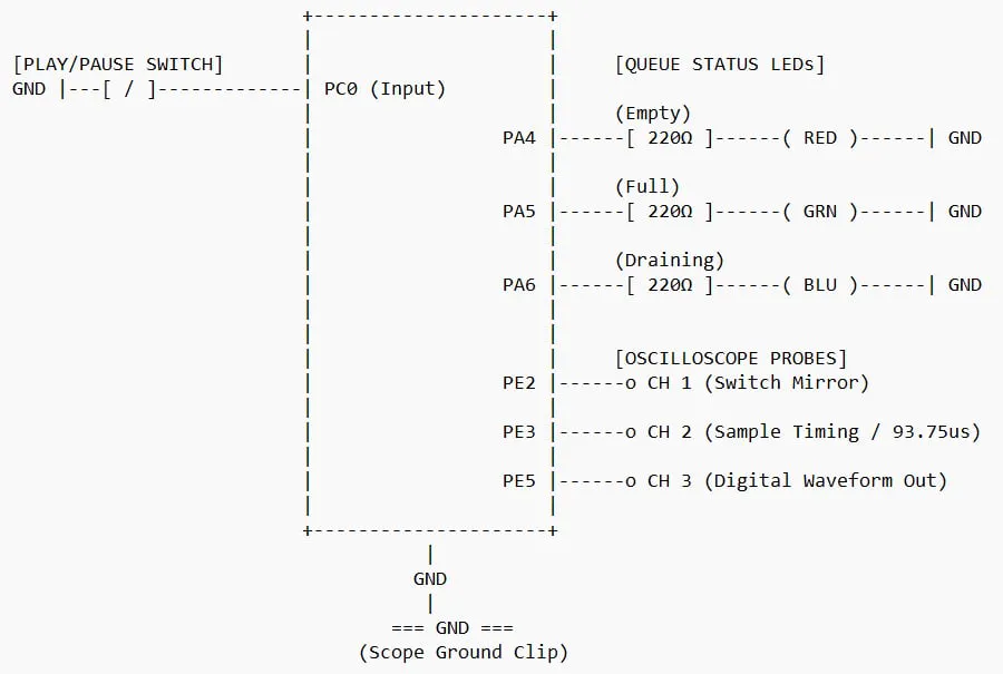
Visualizing and debugging such an asynchronous system requires an elegant telemetry strategy, combining physical visual indicators with high-speed digital diagnostics. In this system, state tracking is exposed in real time through a tri-color LED array on Port A. A red LED signifies queue starvation (empty buffer), alerting the engineer that the Consumer is demanding data faster than the Producer can supply it. A green LED indicates backpressure (full buffer), showing that the Producer has maxed out its buffer allocation. A blue LED denotes a healthy, active equilibrium, where data is smoothly draining between full and empty states. Simultaneously, dedicated debugging pins on Port E provide hardware trigger points for an oscilloscope or logic analyzer. By mirroring the switch state on PE2 and toggling a timing pin on PE3 every time a sample is processed, an engineer can visually confirm on a scope screen that the output signal remains perfectly constant even while a human operator blocks the software loop.
Ultimately, this laboratory project demonstrates the foundational principles that underwrite modern Real-Time Operating Systems (RTOS) and professional firmware design. By moving away from primitive, CPU-blocking structures and embracing an interrupt-driven, queue-buffered topology, the firmware achieves true concurrency. The microcontroller successfully isolates the timing-critical task of analog synthesis from the unpredictable latency of human inputs, resulting in a predictable, efficient, and robust embedded system capable of high-fidelity performance.


Comments