

Hardware components | ||||||
 |
| × | 1 | |||
 |
| × | 1 | |||
| × | 1 | ||||
| × | 1 | ||||
Software apps and online services | ||||||
 |
| |||||
In embedded systems engineering, it is easy to take serial communication for granted. We open a serial terminal, type a command, and watch data instantly appear on the screen. But what actually happens at the hardware level during those fleeting microseconds?
To answer this, this project profiles the performance of a UART (Universal Asynchronous Receiver-Transmitter) link. Using an RT-Thread RT-Spark Development Board (powered by an STM32 MCU) and a digital oscilloscope, we analyze physical bit timings, mathematical computation overhead, and real-world processing delays at the microsecond scale.
The Application: Echo, Compute, and BroadcastThe core of the project relies on a firmware application that listens for user input via serial communication, processes it mathematically, and broadcasts the output across multiple channels.
The main execution loop operates as follows:
Listen & Echo: The firmware polls USART2. Every character typed in the terminal is caught, immediately echoed back to the host computer so the user can track their input, and pushed into a string buffer.
- Listen & Echo: The firmware polls
USART2. Every character typed in the terminal is caught, immediately echoed back to the host computer so the user can track their input, and pushed into a string buffer.
Trigger Condition: Once a carriage return (\r) or newline (\n) character is detected, the string capture is finalized.
- Trigger Condition: Once a carriage return (
\r) or newline (\n) character is detected, the string capture is finalized.
Compute: The firmware converts the text buffer into a floating-point value using atof() and computes its square root using the standard C math library's sqrt() function.
- Compute: The firmware converts the text buffer into a floating-point value using
atof()and computes its square root using the standard C math library'ssqrt()function.
Dual Broadcast: The formatted calculation string—e.g., Sqrt(16.00) = 4.0000—is packaged up and simultaneously transmitted over bothUSART2 and USART1.
- Dual Broadcast: The formatted calculation string—e.g.,
Sqrt(16.00) = 4.0000—is packaged up and simultaneously transmitted over bothUSART2andUSART1.
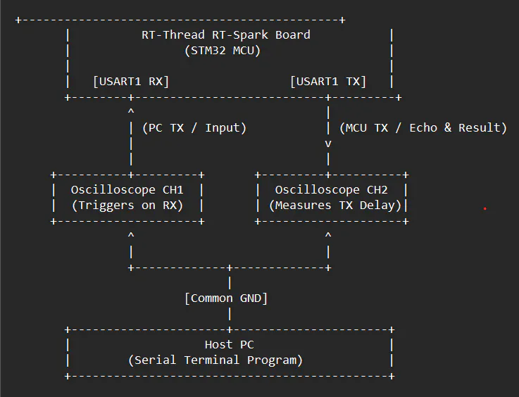
To capture these microsecond transitions, a digital oscilloscope was connected directly to the RT-Spark board's communication pins:
Channel 1 (Yellow): Hooked to the USART2 RX line (monitoring incoming data from the host PC).
- Channel 1 (Yellow): Hooked to the
USART2 RXline (monitoring incoming data from the host PC).
Channel 2 (Blue): Hooked to the USART2 TX line (monitoring outgoing data leaving the MCU).
- Channel 2 (Blue): Hooked to the
USART2 TXline (monitoring outgoing data leaving the MCU).
Because UART transmission lines idle high, the oscilloscope was configured to trigger on a falling edge on Channel 1 to catch the exact moment a packet sequence ends.
Experimental Findings & Performance MetricsRunning the system initially at a baseline of 57, 600 baud, the scope captured several critical parameters:
1. Validating Bit Width MathThe minimum pulse duration (the width of a single bit) on the transmission lines was measured. At 57, 600 bits per second, the theoretical duration of a single bit is:
The hardware measurements on the oscilloscope perfectly mirrored this value, validating clock configuration and baud rate accuracy.
2. Profiling the Processing DelayThe key metric of this analysis was measuring the exact processing delay. This is the time gap between the stop bit of the final incoming character (the newline) on USART2 RX and the start bit of the very first byte transmitted back by the MCU on USART2 TX.
During this microscopic window, the microcontroller must:
Terminate the string buffer.
- Terminate the string buffer.
Parse the ASCII characters into a double.
- Parse the ASCII characters into a
double.
Execute the sqrt() floating-point operation.
- Execute the
sqrt()floating-point operation.
Format the final string payload using snprintf().
- Format the final string payload using
snprintf().
Initialize the HAL UART Transmit peripheral.
- Initialize the HAL UART Transmit peripheral.
Using the oscilloscope's precision cursors, this entire turnaround sequence was clocked at exactly 8.80 µs.
3. Maximizing ThroughputTo test the limitations of the link, the configuration was scaled up to find the highest successful communication rate. After adjusting the configuration registers, the setup achieved a stable, error-free communication link at 115, 200 baud, effectively halving data transmission times while maintaining 100% data integrity.
ConclusionThis performance analysis proves that what looks like "instantaneous" execution to a human observer is actually a highly structured, precisely timed sequence of hardware states. Measuring a processing delay of just 8.80 µs highlights the speed of modern ARM Cortex-M architecture when handling intensive data-parsing and floating-point math routines.
When designing responsive telemetry systems or real-time control links, capturing real-world propagation and execution delays on an oscilloscope is the key to building deterministic, industrial-grade firmware.


Comments