

Hardware components | ||||||
 |
| × | 3 | |||
 |
| × | 1 | |||
 |
| × | 1 | |||
 |
| × | 1 | |||
 |
| × | 1 | |||
| × | 1 | ||||
Software apps and online services | ||||||
 |
| |||||
Remember the days of dedicated MP3 players? Before our smartphones did everything, having a standalone device just for music was the ultimate tech accessory. For my Firmware Programming final exam project at Mindanao State University - IIT, I decided to take a trip down memory lane and build a Personal MP3 Player from scratch.
But I didn't want this to be just a simple Arduino loop. I wanted to build an industrial-grade, multithreaded system using an STM32 microcontroller and FreeRTOS.
Here is the story of how I turned a bare-metal RT-Spark board into a fully functional, multitasking audio player.
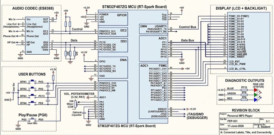
The Vision and The HardwareThe goal was clear: build a device capable of playing 8 different tracks, complete with a physical volume knob, an LCD interface, diagnostic RGB LEDs, and a unique track-selection mechanism.
To bring this to life, my hardware stack included:
The Brains: An STM32F407ZG on the RT-Spark board.
- The Brains: An STM32F407ZG on the RT-Spark board.
The Voice: An ES8388 Audio Codec, communicating via I2C for control and I2S (with DMA) for smooth, uninterrupted audio streaming.
- The Voice: An ES8388 Audio Codec, communicating via I2C for control and I2S (with DMA) for smooth, uninterrupted audio streaming.
The UI: An FSMC-driven LCD display and onboard RGB LEDs.
- The UI: An FSMC-driven LCD display and onboard RGB LEDs.
The Controls: A standard potentiometer and an array of push buttons hooked up on a breadboard.
- The Controls: A standard potentiometer and an array of push buttons hooked up on a breadboard.
I wanted the user interaction to feel like a real piece of hardware hacking. Instead of a basic "Next/Previous" button setup, I implemented a binary selection system.
As you can see in the project video, I wired up a row of tactile push buttons on a breadboard. By holding down a combination of three buttons (BTN2, BTN3, and BTN4), you input a 3-bit binary number (0 to 7) to select one of the 8 hardcoded tracks.
Once the combination is dialed in, pressing the primary select button queues the song. The system immediately provides visual feedback: the LCD prompts "CONFIRM TRACK" and the onboard RGB LED snaps to Green. You then have a tense 5-second "grace period" to confirm your choice. If you do, the music starts. If you don't, the player simply resumes what it was doing. It’s a highly deliberate, tactile way to interact with the device!
Taming the Chaos with FreeRTOSWhen you are streaming audio, reading analog volume knobs, polling buttons, and updating an LCD all at the same time, a standard while(1) loop quickly turns into a sluggish, lagging mess. To solve this, I deployed FreeRTOS to divide the workload into three distinct, cooperative threads:
The UI & Audio Engine (Thread 1): This thread is the heavy lifter. It safely updates the LCD screen, showing track names and the system status (like "PLAYING" or "STOPPED"). It also drives the crucial RGB LEDs—shining Blue when a track is actively playing, Red when playback is stopped, and Green during the track selection phase.
- The UI & Audio Engine (Thread 1): This thread is the heavy lifter. It safely updates the LCD screen, showing track names and the system status (like "PLAYING" or "STOPPED"). It also drives the crucial RGB LEDs—shining Blue when a track is actively playing, Red when playback is stopped, and Green during the track selection phase.
The Input Poller (Thread 2): This thread constantly watches the physical breadboard buttons. It calculates the binary track selection, manages the 5-second timeout logic, and watches a dedicated button to instantly halt or resume the music.
- The Input Poller (Thread 2): This thread constantly watches the physical breadboard buttons. It calculates the binary track selection, manages the 5-second timeout logic, and watches a dedicated button to instantly halt or resume the music.
The Volume Monitor (Thread 3): A dedicated thread watches the potentiometer wired to the breadboard. As shown in the demo, a simple twist of this knob instantly adjusts the output volume , scaling the raw ADC value into a clean percentage pushed to the audio codec.
- The Volume Monitor (Thread 3): A dedicated thread watches the potentiometer wired to the breadboard. As shown in the demo, a simple twist of this knob instantly adjusts the output volume , scaling the raw ADC value into a clean percentage pushed to the audio codec.
The moment I plugged in my speakers and heard the synthesized notes play flawlessly while I adjusted the physical volume knob and watched the LCD update in real-time—that was pure maker magic.
Using DMA (Direct Memory Access) for the audio meant the CPU didn't even break a sweat streaming the music, leaving plenty of processing power for the RTOS to seamlessly juggle the interface and inputs.
This project was a massive learning experience in memory management, hardware interrupts, and real-time operating systems. It proved that with the right architecture, you can make a single MCU gracefully juggle a dozen tasks at once!


Comments