


Hardware components | ||||||
 |
| × | 1 | |||
 |
| × | 1 | |||
 |
| × | 15 | |||
 |
| × | 1 | |||
 |
| × | 1 | |||
| × | 1 | ||||
| × | 1 | ||||
| × | 3 | ||||
Software apps and online services | ||||||
| ||||||
 |
| |||||
| ||||||
Hand tools and fabrication machines | ||||||
| ||||||
For Hackercamp WHY2025 (What Hackers Yearn for), I’ve made a Ghettoblaster with TV and Spotify playlist. But there is something (un)ethical about this.
Hackercamp WHY2025 is a camp with 3750 nerds camping in tents. Showing off what they know about security. But also LEDs, Lasers and Fire (or a combination of all!). Enjoy a musical tribute, the performance of Symphony of Fire or the Fire Wall.
With a group of friends we are the 80’s Party. The word eighties is pronounced in the same way as the Dutch word ethisch, which translates to ethics.
This television scans for your devices, but did you consent to that? That is the discussion starter!
The big plan for the 80's GhettoblasterIn preparation for the WHY2025 camp, we jotted down the wish to have some music in our village tent. We started composing a Spotify playlist with the best (and worst) 80’s music. My take was to provide some 80's vibe and get a Boombox or Ghettoblaster. My initial plan, was to buy one and turn that into a jukebox. Simple, no extra features, just a jukebox.
While scrolling through a Dutch marketplace website, I noticed the ghettoblasters that looked like what I wanted, were all quite expensive. Most of them were refurbished and sold as good working retro. What I needed, was a broken one, where just the outside looked good. Worth a few euros, not hundreds...
Then suddenly, I did spot an advertisement for a 1983 Portable CRT Television. Same size as a radio, but with a screen! Didn’t hesitate and made an appointment to pick it up. So now I was the proud owner of a CRT television.
I started with analyzing the functions of the television by looking at it, and then opened up the backside.
Warning: a CRT is a HUGE capacitor! (more on that later)It can contain enough energy to shock you. Do not touch the tube, be smart, and discharge it first. Do not attempt the screw-driver trick, but invest a bit in a high voltage probe to discharge. You will thank yourself later for that ;)
What do I have at hand here;
- Brand: Philips Combi TC-10
- CRT Television, black and white, 23 cm / 9 inch diameter
- AM/FM Radio
- Cassette player and recorder, rubberband is dissolved
- Antenna/RF In on the back
- Audio Line In on the side
- 2 loudspeakers on the front
- Build in stereo microphones
- 6 channel presets (can be tuned with scroll wheels)
- 9 kilograms!
Then I did search for manuals and other documentation. At the Radio Museum website, I did find the blueprints of all the circuits that are inside this television. That always comes in handy when repurposing retro devices!
Now I have this CRT Television in hands, I did rethink the plan. Because just being a jukebox didn’t feel good for such a cool television. I can show the album art or even videoclips on screen at least. Downside of the television, was that its design (2 small loudspeakers) wasn’t made to fill a village square with loud music, it would maybe be loud enough for a small living room. The Ethics Party vibes were expected to be more intense.
Ethics wise, I did remember the PaxCounters to count people (allowed with the correct constraints of data storage), but also the case from the Community of Eindhoven where they tracked people in a shopping center (not allowed and they got a huge fine for doing this). Maybe I can do something related to this, of course within the range of the allowed.
The plan now started to get new shapes: a jukebox with album art in its core. Providing an audio-out so that it can be connected to a bigger audio installation.
For the ethics part, I’ll scan for WiFi and Bluetooth signals that are send out by phones, laptops, smartwatches, headphones, etc. And a radar will scan for a person in front of the ghettoblaster. What I will do with these signals, not sure yet, that will be crystallized out when I’m at that stage of the project. At least it will have to have an effect on the audio output.
To cut this plan down into pieces, I made up a list of tasks:
- Part 1: get video displayed on the television
- Part 2: get Spotify running and showing on the television
- Part 3: scan for WiFi and Bluetooth and deliver this to the Raspberry
- Part 4: build audio effects based on the WiFi and Bluetooth scanning results
- Part 5: build the person scanning radar and a display
- Part 6: add visual response, with LEDs and more shiny things
This television is a good old CRT (Cathode Ray Tube), meaning it weights a LOT (it is made of thick glass) and is HUGE (25 cm deep, for a screen of 23 cm diagonal). Nothing compared to the LCD/TFT/OLED/etc we have today. Also, the technique is very different. There is used a high voltage (110 volt in this television), to charge the Cathode.
This makes the CRT tube an enormous capacitor, which can hold a charge of hundreds to thousands of volts, depending on size of the tube. So be very careful with touching all this! On the internet you can find guides that use a screwdriver to discharge with a bang. Don’t try that. Just buy a good high voltage probe for this, I've used this one. It does cost you a bit, but also saves you from getting severe damage to yourself...
If you are in for a detailed explanation on how a CRT television works, you can read this page.
On the back of this television, there is one input for RF (Radio Frequency), you can plug in a small antenna. But RF television broadcast signal is not available anymore for years now, it is all replaced by DVB-T (Digital Video Broadcasting - Terrestrial). Don’t mix RF with COAX or Composite, it all has something to do with video and uses similar connector sizes, but they are not compatible with each other.
A Raspberry Pi can output HDMI video by default, but there is still a Composite output available. See below picture: With the original Raspberry Pi 1 (left), this was a yellow connector. From Raspberry Pi 2 to 4 (middle), this was moved into the headphone jacket on a 4th section of the plug. With Raspberry Pi 5 (right), it is moved into its own PIN header, but you need to solder it onto the board yourself.
As RF is not the same as Composite, I had to do conversion steps. With my Raspberry Pi 4, I could Frankenstein this in the following way: Raspberry Pi => 4pin 3.5mm headphone jacket => split the wire into a Composite plug => use a Composite to RF converter => plug that into the RF IN of the television. Of course, I did try this to see if the television did work and if the Raspberry Pi was able to output video. It did work. Good, next step!
There are many 4 pin 3.5mm headphone jack cables, but there is no real standard. The order or wires is different per device, manufacturer and seller. Read the correct explanation here.
Time to follow the path of my video signal, from connector at the back, to the tube. I've looked at both the blueprints and at the hardware. Let me explain how this works.
This is the inside of the television:
- 1. We enter the television on the black board with the RF antenna plug, which connects to the brown board on the edge at the right.
- 2. The tin box is where the RF signal is made into a clean signal.
- 3. The green board sticked to the front (also still at the right), is where channel selection and tuning is done on the front of the television, signal coming out is clean and just 1 channel.
- 4. Then on the brown board there is done an RF to video + sync signal conversion. Which is with a cable guided down to the main board on lower half in the middle. Some last tweaking is done here; the fine tune switches that stick out of the back of the television. On the main board the video and sync signals are translated into Horizontal and Vertical signals. On the main board, there is also a voltage booster to injected 110 volts into the CRT tube.
- 5. From the main board, a set of cables go to the green board in the middle, which is at the back of the CRT tube. This does move the “dot” on screen from left-to-right and top-to-bottom.
But as a true Hackster.io member, the Frankenstein solution was just temporarily. Time to bypass all of this, and get proper Raspberry Pi to CRT signal conversion built! This is where the blueprints come in handy. It shows voltage levels and the wires that I need. As I want to bypass this mix of conversions, my best option is to get rid of the black, brown and green boards on the right side of the television.
To follow the same in the blueprints, I've colored each PCB, and marked the connection points between the PCBs:
The green part in this blueprint is the main board at the bottom of the television. I can get right of the grey, yellow and orange parts. Purple and blue are what is directly connected at the tube.
As explained; the cable that goes to the main board, carries a Video and Sync signal. Place where to feed that, is the blue dots on the edge between yellow and green part in above picture.
This way I can feed my signal right into the main board at the bottom, and I don’t have to play with the high-voltage parts. That means I have to take Composite Video from the Raspberry Pi (between 0 and 1 volts) and translate that into Video (between 5 and 6 volts) and add Sync (at 0 and 9 volts). Sounds easy! Isn't it? No...
Many guides on the internet come close, but none nailed my exact use case. What I did design:
Logic was sorted out, but the size of capacitors, I was not yet clear on. First versions were on a breadboard, so I could exchange the capacitors. I did even buy a oscilloscope to see what the original signal looked like, and how my signal looked like. This was a lot of playing, changing, more playing, more changing, etc. But in the end, I did find the correct values for my schema.
This custom PCB is made with my Snapmaker A350 with the CNC tool. No waiting time for a factory, mail from China, just wipe off the dust, solder the components on it, and you are ready for a test. It works! I can show my Raspberry Pi screen on the television! Part 1 of my project is done after literally 2 months of analyzing blueprints, googling options, testing solutions and fiddling with capacitors.
Yellow jumper is so that it could be replaced with wires for a reset-switch, and the configurable capacitor is to configure a timeout after power-on of the television.
Part 2: get Spotify running and showing on the televisionHow do you run a Spotify player on a Raspberry Pi, with the option to play with sound effects later on? I did explore several media center options, and the winner for this type of project is Volumio OS. Reason is that it takes the Raspberry OS at its core, without the desktop. This way it still gives the option to use Python, GPIO pins and the Composite out. And the audio uses a configurable DSP, more on that later. For sound output, I'm using an HifiBerry DAC Hat.
In plain Raspberry OS, it is relatively simple to add Composite Video as the output. With Volumio you need to follow slightly different commands and the order of enabling is very precise. If you do it in the wrong order or wrong command, you will end up in a loop that is hard to exit. Use these steps:
- Download and flash Volumio
- Change the /boot/cmdline.txt file. I don't remember the exact change, but probably the last string "use_kmsg=no" which disables boot-messages in Volumio:
splash plymouth.ignore-serial-consoles dwc_otg.fiq_enable=1 dwc_otg.fiq_fsm_enable=1 dwc_otg.fiq_fsm_mask=0xF dwc_otg.nak_holdoff=1 quiet console=serial0,115200 console=tty1 imgpart=UUID=7f0c0e47-027d-47ad-bd0c-5159b014252e imgfile=/volumio_current.sqsh bootpart=UUID=10D8-1DF5 datapart=UUID=307f8728-204c-4df1-9dcc-f9fb9dec6fbe uuidconfig=cmdline.txt pcie_aspm=off pci=pcie_bus_safe rootwait bootdelay=7 logo.nologo vt.global_cursor_default=0 net.ifnames=0 snd-bcm2835.enable_compat_alsa= snd_bcm2835.enable_hdmi=1 snd_bcm2835.enable_headphones=1 loglevel=0 nodebug use_kmsg=no- Change the /boot/userconfig.txt file to enable the Composite video and disable HDMI. This also adds a second i2c bus as the first one is used by the HifiBerry DAC.
# Add your custom config.txt options to this file, which will be preserved during updates

enable_tvout=1
display_auto_detect=1
dtoverlay=vc4-fkms-v3d,cma-384,composite=1
sdtv_mode=2
sdtv_aspect=1
sdtv_disable_colourburst=1

dtoverlay=i2c-gpio,bus=4,i2c_gpio_sda=24,i2c_gpio_scl=23- Install plugins: FusionDSP, Spotify, AutoStart, Now Playing and Touch Display
- Connect to your Spotify account
- Update the layout of the screen in the Now Playing plugin, this will be a trial-and-error game to get the layout that fits you best. Be creative!
Now you have: a media player running Volumio that outputs the Album Art on screen and a web-site where you can see the playlist and can queue tracks.
Part 3: scan for WiFi and Bluetooth and deliver this to the RaspberryEach WiFi connected device, does have a unique MAC address. When (trying to) making a connection, it shares this address to be able to get a response. Mobile phones do usually change their MAC address every so many minutes/hours, to make it impossible to track them, as the address is then always different. My goal is not to track, but to see the number of unique devices around me at a certain point in time. I’m not going to store MAC addresses for a long time, I’m only counting, so my storage is for 60 seconds max. After that, they are removed from the buffer.
At the start of the project, I had expected that I could use the Raspberry Pi to scan for the WiFi and Bluetooth. But to avoid audio stuttering and as I needed to use the WiFi for the Volumio connection to Spotify and provide the website for queuing tracks, I could not play too much with the WiFi part.
That made me decide to use an ESP32 for WiFi scanning. But that has the downside that it can only connect and scan at 1 channel at a time. In Europe you are allowed to use all 13 WiFi channels on the 2.4 GHz band. I could hop channels and scan them 1-by-1, so I could scan them all 13 from 1 device. But at each point in time, I’m only scanning 1 channel, missing activity on the other 12. Does not sound like a big deal, but it takes away the immediate response to the number of devices around. That made me decided to use 13 ESP32's and let each of them scan a separate channel.
Looking at the other side of the spectrum: a phone connects to a router on say channel 4. As a backup it also tries channel 3 and 5. And on top of that, it also sends data regularly on all 13 channels, polling for new routers. Meaning my 13-channel data providers will have duplicates. I’m solving that by adding a 14th ESP32 to collect the data from the 13 scanners and only keep the latest appearance of a MAC address for max 60 seconds. This also allows me to make a clear cut between the WiFi scanning/mac address ‘storage’ and the Raspberry Pi, which only needs a number.
So now I have 13 ESP32's scanning WiFi and 1 ESP32 collecting data. This should then be sent as a number to the Raspberry Pi. But how do you communicate between all these devices in a fast way and without building a protocol yourself
With I2C (Inter-Integrated Circuit) of course! This is a communication protocol that can be used between a server (master) and devices (slaves). Meaning the WiFi Scanners are an I2C device, this will be handled by 13 XIAO ESP32-C3 from Seeed Studio. The WiFi Collector needs 2 I2C connections; one as a server and one as a device. The C3 model could not handle a second I2C connection, so the Collector is a XIAO ESP32-S3 from Seeed Studio. The Raspberry Pi is then the last server.
Quick rundown of how this works:
ESP32 Wifi Scanners:
- Constantly scan for WiFi devices on their dedicated channel
- Stores MAC address and the RSSI in a temporary CircularBuffer
ESP32 WiFi Collector:
- Polls the 13 WiFi Scanners for their last received MAC Address and RSSI from their CircularBuffer.
- If an existing MAC is found; Update the last received time to current time. If the RSSI is better than the last one, update this in its own Buffer.
- Every few seconds scan the Buffer for last received times older than 60 seconds and clear these
Raspberry Pi
- Poll the WiFi Collector for the number of devices currently in its Buffer.
The same logic is applied for Bluetooth scanning. With the difference that for Bluetooth there is only one channel. Meaning the function for Scanner and Collector are combined: There only is a Buffer with the last received time and best RSSI combination for the MAC addresses. This is also done on a XIAO ESP32-C3 from Seeed Studio.
Task 4: build audio effects based on the WiFi and Bluetooth scanning resultsVolumio works with a standard DSP (Digital Signal Processor), but can be extended with CamillaDSP. And CamillaDSP has the option to use APIs or web socket connections to change its settings on the fly. This is the ideal option to introduce sound effects based on the scanned WiFi and Bluetooth devices. But what and how?
I do have a buffer with 2 datapoints for each entry: time last received and RSSI. If I look at the full dataset, that will be 60 seconds and an RSSI of at least -90 DB. Remember: RSSI is always shown as a negative number:
- -30 = Perfect
- -31 to -50 = Excellent
- -50 to -67 = Good
- -67 to -80 = Fair
- -80 to -90 = Weak
- below -90 = Unusable.
On the television, I'll use 3 knobs for filtering this dataset: Bluetooth RSSI, Time Range and WiFi RSSI.
When I filter for an RSSI higher (better) than -80 (so -79, -70, -50 etc), it means that probably each scanned device is counted. If I change the RSSI filter to -60 (looking for better signal), I do probably see less scanned devices. If I then also shorten the time range, the number of found devices is even smaller.
As I can never predict the number of devices at a certain location (at home: 15 devices or at WHY2025: 250 devices), these 3 filter knobs are the way to find a the sweet spot for a regular sound at the location you are at. Any change in number of devices will then alter the sound. As I do have 2 scanned signal types (WiFi and Bluetooth), I can adjust the Bass and Trebble ends of the equalizer with these to numbers.
I'm keeping the center channels neutral, Bluetooth has an effect on the 6 outer channels at the left of the spectrum (bass), and WiFi has an effect on the 6 outer channels on the right end of the spectrum (treble). The center 3 channels are not adjusted.
While turning the knobs, I set the thresholds in code. And while receiving new buffered WiFi and Bluetooth data, my code writes an updated custom_camilladsp.yml file to CamillaDSP to set the new values of the equalizer.
Part 5: build the person scanning radar and a displayAs a bonus, there is added an Rd-03D 24GHz radar (Silicon Microelectronics' S5KM312CL chip) that senses if a person is in front of the Ghettoblaster and if that person is on the left or right. The radar is connected to its own Seeed Studio ESP32-C3 that registers the movement and let 2 light rings around the speaker glow. With I2C the balance is communicated to the Raspberry Pi, which in turn uses this to send the sound balance to the CamillaDSP API.
See the glowing speakers in action:
Task 6: add visual response, with LEDs and more shiny thingsBecause the radio frequency control was removed, I did now have a long transparent guide screen which is empty. That is the ideal fit for an LED-string. It has to have small LEDs that are close to each other. I found a Ultrathin WS2812B LED strip which is just 2.7mm wide and has 160 LED/m. A perfect fit for the Ghettoblaster (although sadly 1 LED is defective apparently).
On top of the radio, there are 3 potentiometers, originally for Tone, Balance and Volume. Pimoroni has potentiometers with built-in RGB LEDs. These will be used for filtering the WiFi RSSI, Bluetooth RSSI and time range. They are I2C based, so you can just send the color and request the current value. Easy!
On the top there were also 3 rockers to select Mono/Stereo/Spatial, MW/FM and Television/Tape/Radio. I’ve reused the same switches but mounted them on a new PCB. To light everything up, I’ve added RGB LEDs to each switch. They are now purposed for: Spatial: uses the Radar values, Stereo: just stereo, Mono: just mono. FM: uses the Bluetooth and WiFi data, MW: no Bluetooth and WiFi data used. Radio: LED strip shows the equalizer effect, Tape: shows a full rainbow (FM in disco, MW in gradient), TV: shows a nightrider like animation (FM in rainbow, MW in red).
The buttons for the tape-deck also got a new purpose! Play now (you guessed it) starts playing the music. Stop mechanically releases Start. FWD and REV also got switches for their original functions. Pressing these buttons sends the command to Volumio to Start/Stop, Skip Forward or Skip Back. As this now requires quite some pins, I've added an MCP23017 IC which has its own 16 pins and connects to the Raspberry Pi with I2C.
The sound of the 3.5mm jack on the HifiBerry DAC is not that load, it is meant for headphones. That is why I've added an amplifier to boost the sound for the speakers a little bit. That also means the volume control is on the amplifier. And I could use the large radio frequency tuning knob on the right side. This is now the volume knob.
The original tape motor is still there and wired up. When you push down the Play button, the tape starts running. I change a cassette by removing the tape, and running an elastic band between the rolls. Now it can play forever!
To show current settings, there is an OLED display mounted behind the window that previously hid the channel tuning. The display works with the U8g2 library.
Just above the channel tuning, there are 6 switches for channel selection. These are now used for screen function selection; Device name, Song info, Radar balance, Bluetooth info, Wifi info, and a placeholder for who knows! They kept their original lights but replaced them with bright LEDs.
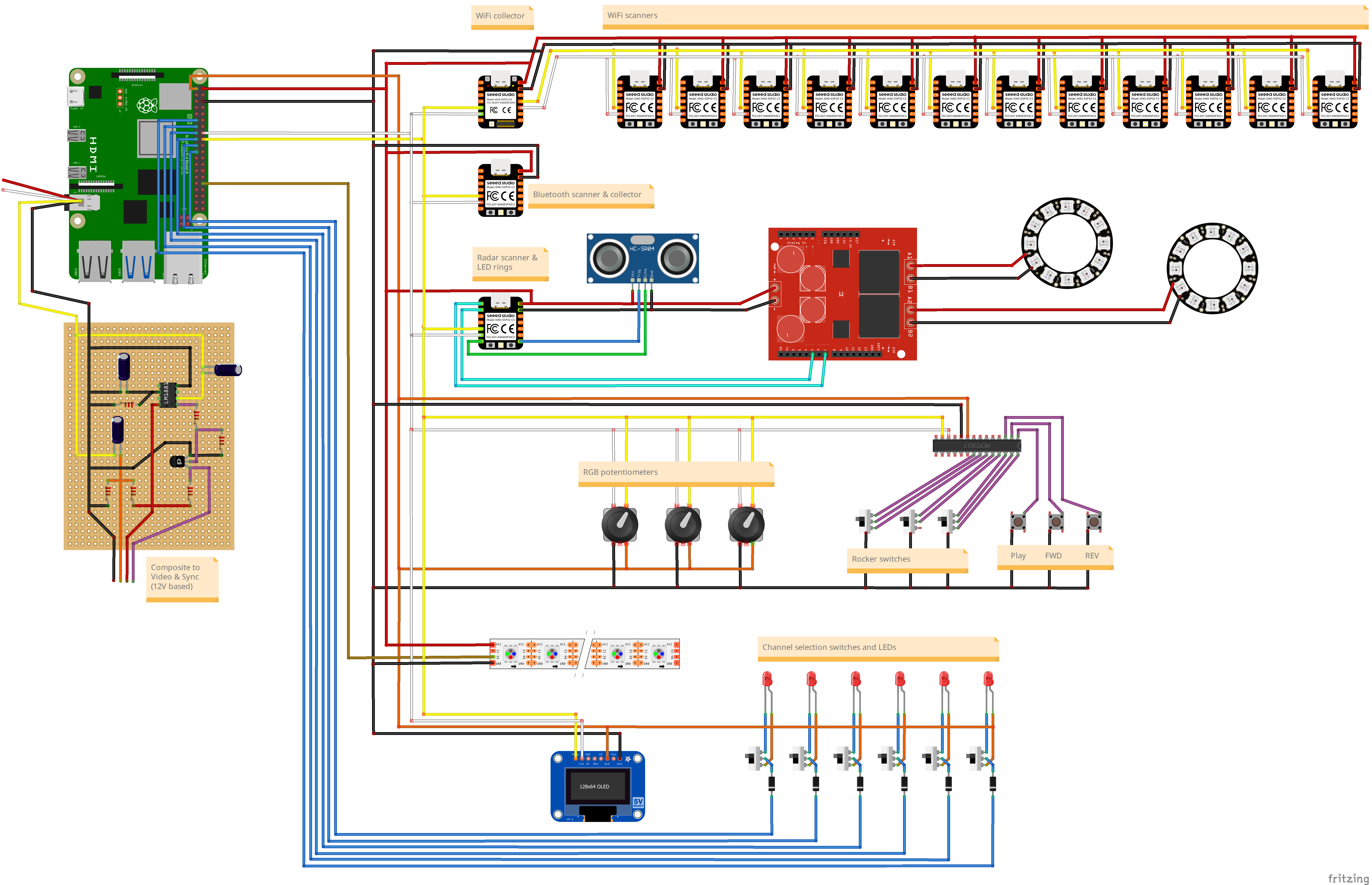
After all this work, replacing almost all internals, the full Fritzing diagram now looks like this:
And the best; the Ghettoblaster now plays music and shows you the Now Playing cover on screen.
But did you consent that it scans for your WiFi and Bluetooth devices? That with a Radar, it scans for presence of you? Maybe you consent with that because you don't care. Maybe you do not want a big brother. But above all, this is to stir up that discussion. We should not take everything for granted.
With the gathered WiFi, Bluetooth and radar data, the sound output is adjusted. More people, weirder sounds. This is a demo recorded during the WHY2025 camp while there were about 250 WiFi devices scanned:
Second demo of the (un)Ethical Ghettoblaster, this time on the workbench, but has a bit better demo of all functions:


Comments