


Hardware components | ||||||
 |
| × | 1 | |||
| × | 1 | ||||
| × | 1 | ||||
| × | 1 | ||||
| × | 1 | ||||
| × | 1 | ||||
| × | 1 | ||||
| × | 1 | ||||
| × | 1 | ||||
| × | 1 | ||||
| × | 1 | ||||
| × | 1 | ||||
| × | 1 | ||||
| × | 1 | ||||
| × | 1 | ||||
Software apps and online services | ||||||
| ||||||
| ||||||
Hand tools and fabrication machines | ||||||
 |
| |||||
 |
| |||||
Are you ready to take your communication device go off-grid? Introducing Meshtastic 20.25! Made to go camping or hiking, during a festival or just commuting to the office.
In the core a Seeed Studio Wio Tracker L1. On top of that added a mini keyboard from a TV remote, E-ink screen for power-saving visuals and a vibration motor for instant alerts. All housed in a case with a solar panel on the back!
Originally Meshtastic devices were made to work as a Bluetooth companion device connected to a phone with a messaging app. But what if you don’t want to carry a phone on your hike? That’s fine, the Wio Tracker L1 devices have a single menu button and a tiny joystick, so you can twist your thumb for minutes, to twiddle something down.
Not really useful if you are hanging on the edge of a cliff and want to type an SOS message to your friend… Let’s include a keyboard! And maybe even an SOS button?
During your camping trip you go off-grid for multiple days. But the commonly used always-on-OLED-displays consume battery capacity all the time, even when you are not looking at your device. That is why I will use an E-ink screen that only refreshes when it is needed. And to charge the large internal battery on-the-go, just flip it over and hold it in the sun, there is a solar panel on the back!
While you lay down in your beach-chair, your FOMO starts creeping up. Did you miss a message? I got you covered, there is no need to keep refreshing the screen to see if there are new messages, a vibration motor will be added to work together with the buzzer to instantly alert you of something new!
Meshtastic off-grid communication, always available, always useful, always fun! Welcome to 20.25 ;)
What is Meshtastic?In very short phrasing, cutting a lot of corners; it is a communication framework, with a lot of features that make it magical!
Meshtastic sends its data on the license free bands, so you don’t need to be a HAM. In each region of the world, the frequency to use is a bit different. For example, in Europe 433MHz and 868MHz, in North America 915MHz. These are slow bands due to the (relatively) low frequency, but that also means you can reach a long distance. Because it is slow, you will have to cleverly design your protocols to use as less airtime as possible, and still making sure your message will be received crisp and clear. The protocol used in Meshtastic, is LoRa, which stands for Long Range. This protocol is based on Chirps instead of Pulses. Clever thinking!
The additional clever thing that Meshtastic did, is in its name: it is based on a Mesh network. Each device repeats the messages that are not meant for itself. That means the already long range can even become longer. Records are into the hundreds of kilometers!
Ok, now we have a device that can send messages over a mesh network to other devices. How do you get your message send? Classically, you would use a mobile phone with a Bluetooth connection, and use the Meshtastic app there to type and read messages. Most Meshtastic devices have a little OLED screen to show status on. Some devices, like the Seeed Wio Tracker L1, have additional buttons or joysticks to do more with this menu and even create messages on the tiny screen.
That is where this project wants to add a bit more. No need for the mobile phone, everything in this single device!
Project planning - anticipated stepsIn the coming weeks, I'll design and build this Meshtastic device, combining hardware, to make the ideal communication tool. These are the steps that I will follow in this project:
- Step 1: Selecting the parts
- Step 2: First design to see if my idea fits the parts.
- Step 3: All parts are ordered, they will come in the mail one by one.
- Step 4: Create a model in Fusion 360 of each part received.
- Step 5: When all parts are in, put them all together in real life to see if the device works as expected.
- Step 6: Move all parts into the right position in Fusion 360 and build the ideal casing around it.
- Step 7: 3D Print the design
- Step 8: Test, Try, Debug, Fail or Succeed. Go back to step 6 and repeat (until satisfied).
- Step 9: Take Meshtastic 20.25 out into the wild!
Will keep the updates coming here, so follow along!
Step 1: Selecting the partsActually, read the first chapter again, that is my brain dump of what my vision is of the Meshtastic 20.25 and all the parts that I need for that.
Step 2: First design to see if my idea fits the partsAs a start, I've already made some Fusion 360 designs with the first ideas.
Front of the device; a full QWERTY keyboard including numbers and special characters. Top left is a joystick, top right is where the E-ink display goes:
Front cover and keyboard removed, these are the components that need to be placed inside the device: Left the GPS, middle a LiPo battery, right at the back is the Wio Tracker, right at the front is the E-ink display:
On the backside there is a solar panel that covers as much as possible, that might even become the full back panel.
On the Seeed website, the Wio Tracker with E-ink display was in backorder, so I did order the OLED version.
And ordered a similar E-ink and cables plus connectors elsewhere:
At the front I want a full keyboard, with soft keys and not invent it all myself. There exist these mini-keyboards that work as a TV-remote. So I did order one that looks the correct size. Now hopefully it will generate serial data that I can tap into on each keypress. If not, I'll have to work with a matrix and wire that up to an RP2350. Of course the case will be ripped off, using only the rubber keys and PCB.
On the back-side there will be a solar panel. I've chosen one that is close to the size of the keyboard (assuming that is close to the PCB size too), hoping that I can cover the full backside edge to edge. Let's see what will show up in the mail...
This Solar Panel will charge a Lithium Polymer (LiPo) battery. Have one laying in the drawer, with 3500 mAh capacity.
Lastly, there is a vibration motor to be included. Small but mighty!
UPDATE September 2: Received the Seeed Studio Wio Tracker L1 (with OLED screen) in the mail, the Fusion model is already provided by Seeed, but I added colors for better looks.
The delivery of the Wio Tracker also included the LoRa antenna and GNSS antenna. So made models of these to later import in my drawings.
And found a USB-C breakout board in my stash, which I will need to extend the USB port to the new side. Also here, I made the model un Fusion 360.
The design of the case already looks a bit better with these models. Placing comes later when everything is received.
UPDATE September 3: the Keyboard arrived! This thing is complex to model, so that will take a few days. But here are the product pictures already:
Looking at the PCB it might be a bit harder to tap into the serial bus, but I have some alternatives in mind.
UPDATE September 4: created the model of the keyboard. This is how the hardware is as-is, but I'll cut out some unnecessary keys (F1/F2/etc) when it goes to the real design.
Now that I have the size of the main components, it's time for a better drawing! The E-Ink screen is to be added on the top-right, 4 or 6 of the small keys will be sacrificed for that. On the back is the edge-to-edge Solar panel. And this way you can see how the antenna can fold into the casing!
What do you think of this design?
UPDATE September 9: As there are no serial test-points on the keyboard that I can tap into, there are two alternatives: use the USB-dongle (HID device) and 'plug' that into an RP2350, which translates the keystrokes to serial data. Or tap into the keyboard matrix and do the key mapping on the RP2350. The latter does need less power, as we are not transmitting wireless data and having an additional IC running. So Keyboard Matrix analysis to be done!
To "see" the matrix, I first took pictures of both sides of the PCB. Mirrored the picture from the back and overlayed it with a bit of transparency to see all traces and vias:
Then follow all the traces, with vias going from front-to-back and vice versa. This way we can find all the contact points behind the buttons. Many colorful lines, but it makes me understand where I must tap into the matrix to "listen" for keypresses:
UPDATE September 11: more parts received. While doing inspection of the parts, measured all sides and made models of them:
And two items that I made models for last week and even included them in the designs above but didn't upload the pictures yet.
That means all major parts are in now. There are some small things on order, like a USB-C connector (the one pictured above is too large) and two switches to move the on/off and reset to the outer shell.
Step 5: When all parts are in, put them all together in real life to see if the device works as expected.UPDATE September 16: I've spent the past couple of evenings soldering wires to the Keyboard matrix. This is so small! First time this size, so although it is a bit messy, I'm happy. And most importantly, tested all connections, it works! Wires used are 0.2mm enameled copper. With a magnifying glass and lots of patience. No coffee, you will get shaky hands!
Now it's time for the software that will run on the RP2350.
UPDATE September 18: How does a Keyboard matrix work? Look at the image somewhere higher up with the Keyboard and the colorful lines: we have 7 horizontal lines (rows) and 11 vertical lines (cols). Each of these rows/cols are connected to a pin on the RP2350. The row pins will be set as OUTPUT default HIGH, the col pins are an INPUT with PULLUP. When you press a key, on the crossing of the row/col you will create a connection, reporting the input to be LOW.
The program on the RP2350 will run a loop every 500ms to check if one of the crossings has a connection (is LOW). We do that by setting the row pin 1 to LOW and then one-by-one check all col pins to see if one of them is LOW. Then reset the row 1 to HIGH, and set row pin 2 to LOW. This continues in a loop till all rows are checked.
When a LOW is found, this is the key that is pressed. To avoid capturing repeating keypresses, there is checked if the key was already pressed in previous loop. If this is a new keypress, we have a table with the ASCII key characters for each connection in the matrix. This is what we will send over the serial connection from the RP2350 to the Wio Tracker L1.
There are two special keys: SHIFT and CAPSLOCK. I did not include the CTRL, ALT and FN keys as we just need an ASCII keyboard without other specials. In the loop, there is first checked for the SHIFT key. If SHIFT is pressed, we use a different ASCII table for the matrix. This table contains all ASCII codes for the SHIFT logic; on characters that is the capital character, on numbers there is special characters.
If the CAPSLOCK is pressed, this is toggled ON/OFF in a parameter. Again, it will use another ASCII table, as now only the characters will be in capital. The numbers stay numbers. To make it more complex (who doesn't like that!), you can also first turn on CAPSLOCK and then press SHIFT while pressing another key. This inverts capital character usage, but at the same time gives you special characters on the number keys. So, we have 4 different Key Matrixes: normalKey, shiftKey, capsKey, capshftKey.
The code I wrote for this, is loosely based on code from Cameron Coward: 64-Key Prototyping Keyboard Matrix for Arduino. He has a logic shifter for the cols where he needs to set registers, so I had to rewrite this for individual pins. The matrix Cameron is using has 1 dimension only, he multiplies the rows to get to the correct bit. For easier access, my array is 2-dimensional, to point to the exact row/col position. All-in-all, his code was a perfect jumpstart for me to get this working!
[Later while working on the Keyboard matrix, I've completely changed the approach of holding the possible values in array. Code included at the bottom of the page is the updated version]
Little sidenote on getting the RP2350-Mini (as how they call it on AliExpress) working in the Arduino-IDE: add the Additional Boards Manager URL in your configuration:
https://github.com/earlephilhower/arduino-pico/releases/download/global/package_rp2040_index.jsonThen search in the Board list for RP2350 and install this. When uploading your sketch, in the board selection use Waveshare RP2350 Zero. Maybe it is not a 100% correct board configuration, but this worked out for me for the pin allocations.
First time you upload a sketch, make sure the board is in boot mode: press the BOOT button while plugging in the USB. You will get a virtual drive added in your machine. Then upload your sketch as your normal Arduino IDE workflow. Next time you do not need the manual boot process anymore, the sketch upload process will automatically put your RP2350 in boot mode.
Step 6: Move all parts into the right position in Fusion 360 and build the ideal casing around it.UPATE September 19: First test-print done! I must have been sleeping when creating the model for the battery. Just 2 cm off... Other than that there are some tolerances I have to work on, and fine-tuning the printer...
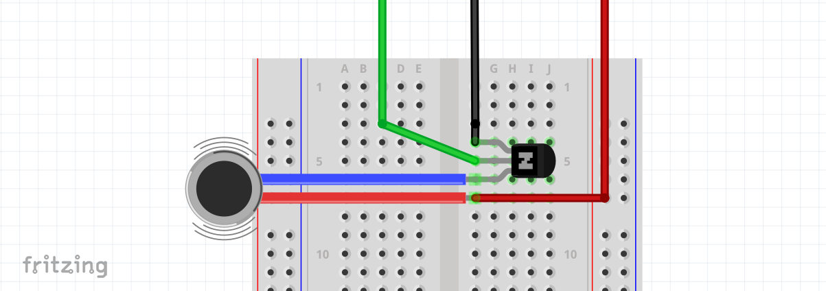
UPDATE September 23: The vibration motor uses more amps than a GPIO pin can provide. With an NPN transisitor (BC548) you can switch full power directly from GND and 3.3V pins. Simple schematics are as following:
UPDATE September 27: I've done lots of rework on the keyboard soldering and code running on the RP2350. The enameled wires did disconnect easily when holding the keyboard in hand for testing. They did rip up the pads of the former chip location. So, new plan! I've scratched off some paint on the via-pads, as these are a bit larger than the traces. And soldered the wires on there. This worked out much better.
Also did a lot of code changes to get the I2C protocol working. I've used the code from M5 Stack for the CardKB as a big helper for that, they had a good idea! The different matrix arrays for normalKey, shiftKey, capsKey and capshftKey are now replaced with one bigger array that covers the variations for all of types in a better overview. While trying the I2C protocol and following both the Serial Monitor of the RP2350 in the Arduino IDE and the Serial Monitor of the Meshtastic Web Flasher, I could see what communication is happening between the two.
At start of communication, the address is requested. For a CardKB keyboard, this is 0x5F. Then the Meshtastic firmware sends a request with ID 4, and expects the keyboard version. CardKB doesn't have a version, so reply with 0x00. Then a request without ID is done, not sure what that is for, also reply with 0x00.
Once that is settled, the Meshtastic keeps asking for a new keypress. When you are typing, I do store all keypresses in a Queue. The onRequestEventI2C does pop each next press from the queue and sends that back. If there was no press registered/queued, send back 0x00.
Pressing keys works like a charm and is fun! Did you also see the CapsLock light?Will add pictures of that later on!
UPDATE October 7: These are the renders from Fusion 360 of the final design. This is what is used in the two YouTube videos (see below) and which are added as STL files below.
UPDATE October 1: Today I have big news! Case is printed, all parts are here and fitted into the case. See for yourself:
Step 8: Test, Try, Debug, Fail or Succeed. Go back to step 6 and repeat (until satisfied).UPDATE October 3: The casing as shown in the video works, but there are always some tweaks to be done
Issue 1; the I2C connector has a clip on the topside which is 2mm thick. Meaning the screen and front-cover is wobbling a bit. Also, the keyboard pcb is flexing a bit. It needs to be clipped a bit tighter. Solution is a ring layer of some mm between body and front. I'll glue it to the front-part such that the keyboard is locked in. Design is made, will be printed tomorrow.
Issue 2; I had assumed the ON/OFF switch is literally ON/OFF. So I did use a switch on the cover with just 2 poles to connect for the ON state. But it turns out the onboard switch is also directing current in the OFF state. I should have used a 3 pin switch instead. That also means I have to de-solder the onboard switch. Within the contest timeline I cannot order a new switch but will do so separately to still make the change on a later time.
Issue 3: the soldered wires for RESET and ON/OFF are too thick/stiff. Will have to replace them with a more flexible cable.
UPDATE October 6: Issue 1 is resolved. The additional ring is printed and clips in perfectly fine! I've also added a lanyard style ribbon and a hook. So now I can clip it to my backpack.
Step 8.x: Meshtastic firmwareBuild your own Meshtastic firmware to use the 4 breakout GPIO pins and our custom keyboard on the Wio Tracker L1
UPDATE October 6: The Meshtastic app will let you connect to GPIO pins for additional functionality. In my project I want to connect to a vibration motor, which is easy to do in the app.
Except... the 4 GPIO pins are not configured in the standard firmware. Let's fix that!
Follow the steps on this page: Building Meshtastic Firmware
- You will need to install Microsoft Visual Studio Code on your computer, follow instructions on this page.
- Then install PlatformIO as an extension, follow instructions on this page.
- Install GIT, if you don't have an account, just install in your operating system. If you do have an account and want to check-in your changes, you can install the extension in Visual Studio Code. Details on installation can be found here
Installation of your firmware development environment is completed now. Next step is to get the Meshtastic firmware.
Assuming you did install GIT outside Visual Studio Code, now clone the Meshtastic repository. Open your command prompt and go to the folder where you want the download. Then use this to clone the Meshtastic firmware:
git clone https://github.com/meshtastic/firmware.git
cd firmware && git submodule update --init
On the Meshtastic Github page, look for the last version (tag) available, at moment of writing that is v2.7.11.ee68575:
Back to the command prompt:
git checkout tags/v2.7.11.ee68575Now we have to add this project to Visual Studio Code and create & upload your first build (without any changes yet):
- Open you new folder in Visual Studio Code. If you do this for the first time, this can take quite some while as PlatformIO will download all the necessary tooling and libraries.
- To select the device you wish to build, open your command palette: Windows: Ctrl + Shift + P or Mac: command + Shift + P.
- Enter PlatformIO: Pick Project Environment, type seeed and select your target: env:seeed_wio_tracker_L1 (optionally with E-ink).
- To build the firmware, run PlatformIO: Build from your command palette.
- Finally, flash the firmware to your device by running PlatformIO: Upload.
Your Wio Tracker L1 will reboot and run on your own compiled firmware.
Now it is time to make your custom firmware with your own changes!
In the Visual Studio Code explorer, open the folder: variants/nrf52840/seeed_wio_tracker_L1/ (OLED version) or variants/nrf52840/seeed_wio_tracker_L1_eink/ (E-ink version). Content should be relatively similar, but there are differences. I'll highlight them where needed.
The files in this folder describe how the board is designed, for example how to connect to the screen and what type and size it is, what GNSS module there is and how it is connected, but also what additional custom functionality it has. This is the place where it should have described the 4 additional GPIO pins, which is the missing bit.
Declaration of board design is the same for both OLED and E-ink versions, but files are completely different. To make this one streamlined documentation, if you are working on the OLED board, copy the VARIANTS.CPP file from the E-ink folder.
Now we are ready to change the variant.cpp file.
First see what and why we are changing; the headers on the board labeled 2, 9, 10, 29 need to be added to our code:
IMPORTANT: on this screenshot taken from the product/sales page, the pins 02 & 10 are on top, 02 & 29 are on the bottom. On the board I received, this is in the opposite way: 02 & 29 on top, 09 & 10 at the bottom. And that is how I did add the pins in this tutorial, and used them!
Looking at the variant.cpp file, we can see that there are 37 pins described (D0 to D36), but we are missing our 4 GPIO pins from the breakout header. The first configurable pin available is D37. Add the following code right after the configuration of D36, on line 86:
// Custom headers
    2,  // D37 P0.02
    29, // D38 P0.29
    9,  // D39 P0.09
    10, // D40 P0.10
Then there is an error in pin assignments for I2C: standard Seeed Studio Grove connectors/cables used for I2C are designed to be GND, 5V, SDA, SCL (black, red, yellow, white). Now look at your board, above the connector there is printed GND, 5V, D1 and D0. At the right a screenshot of another Seeed Studio device, to prove how the SDA and SCL are in order:
That means SDA is on D1 and SCL on D0. According to the board layout diagram, D0 is GPIO1.11 and D1 is GPIO1.12, which translates to pin 43 and 44. But for D17/D18 (line 62/63) this is entered in the opposite way. As it is opposite twice, that eliminates the issue, but I want it to be correct ;)
We will fix that in your file, change these two lines to:
44, // D17 P0.00 GROVESDA (D1)
    43, // D18 P0.01 GROVESCL (D0)
And save your variant.cpp file.
Now open the variant.h file, this one will be different for the OLED and E-ink boards as this file describes which screen you have and which I2C ports to use. In the examples here, I'll document the E-ink variants file first. Changes in the OLED version are similar but have other line numbers, these are also detailed.
Line 13 and 14: change the number of pins from 38 to 42 (OLED version from 33 to 42)
#define PINS_COUNT (42u)       // Total GPIO pins
#define NUM_DIGITAL_PINS (42u) // Digital I/O pins
After line 60, add your 4 new pins (same for OLED):
#define D37 37 // P0.02 Custom header
#define D38 38 // P0.29 Custom header
#define D39 39 // P0.09 Custom header
#define D40 40 // P0.10 Custom header
Pins for SDA/SCL need to be checked and updated as they are used a bit mixed here: D17 is SDA and D18 is SCL.
For both the E-ink and OLED versions, first change is on line 59 and 60:
#define D17 17 // P1.12 GROVE_SDA (D1)
#define D18 18 // P1.11 GROVE_SCL (D0)
The second change for the E-ink version is on line 80 and 81:
#define PIN_WIRE_SDA D17 // P1.12 (D1)
#define PIN_WIRE_SCL D18 // P1.11 (D0)
Second change for the OLED version, is also on line 80 and 81 but with other contents (note the 1 in WIRE1):
#define PIN_WIRE1_SDA D17 // P1.12 (D1)
#define PIN_WIRE1_SCL D18 // P1.11 (D0)
Now you can build and upload your own code!
Open the Visual Studio Code command palette, to build the firmware, run "PlatformIO: Build". And flash the firmware to your device by running "PlatformIO: Upload".
Using your custom header from the app
In the Meshtastic app, go to your Remote Administration and External Notification to set the Vibration config. These are the fields needed:
- Alert message vibra: enable this
- Output vibra (GPIO): I've used GPIO10, which we did list as D40. In the app, enter this as 40.
- Output duration (milliseconds): 1000 or 2000 is good
- Save and your Wio Tracker L1 will reboot
Send yourself a message from another device and feel the vibes :)
Adding the keyboard
A keyboard with I2C is automatically recognized if it has the correct I2C address. I've used the same address as the M5 Stack CardKB keyboard: 0x5F. As we updated the pin assignment for the SDA/SCL pins, our keyboard can be recognized!
But we need to add this in the app too. Go to your Remote Administration and Canned Message:
- Allow input source: enter the value cardkb
- Save and your Wio Tracker L1 will reboot
Use the ENTER key to open the menu and see we automatically got a New Freetext Msg option! When you open that, you can enter your own text right from the keyboard.
But it does not recognize all keys out of the box. We need to map some of them.
Open the file src/input/kbI2cBase.cpp
This file contains all key mappings for multiple types of keyboards. Scroll down to line 362 for the CardKB configuration. We can see here that CardKB does send various Virtual Key commands and not the correct key values that belong to a LEFT, RIGHT key for example. So we must add our mapping here. Good thing is that it does not conflict with the existing CardKB setup. From line 362 to 518, replace with this:
case 0x00:   // CARDKB
    case 0x10: { // T-DECK
        i2cBus->requestFrom((int)cardkb_found.address, 1);

        if (i2cBus->available()) {
            char c = i2cBus->read();
            InputEvent e = {};
            e.inputEvent = INPUT_BROKER_NONE;
            e.kbchar = 0x00;
            e.source = this->_originName;
            switch (c) {
            case 0x00: // nopress
                e.inputEvent = INPUT_BROKER_NONE;
                break;
            case 0x71: // This is the button q. If modifier and q pressed, it cancels the input
                if (is_sym) {
                    is_sym = false;
                    e.inputEvent = INPUT_BROKER_CANCEL;
                } else {
                    e.inputEvent = INPUT_BROKER_ANYKEY;
                    e.kbchar = c;
                }
                break;
            case 0x74: // letter t. if modifier and t pressed call 'tab'
                if (is_sym) {
                    is_sym = false;
                    e.inputEvent = INPUT_BROKER_ANYKEY;
                    e.kbchar = 0x09; // TAB Scancode
                } else {
                    e.inputEvent = INPUT_BROKER_ANYKEY;
                    e.kbchar = c;
                }
                break;
            case 0x6d: // letter m. Modifier makes it mute notifications
                if (is_sym) {
                    is_sym = false;
                    e.inputEvent = INPUT_BROKER_ANYKEY;
                    e.kbchar = INPUT_BROKER_MSG_MUTE_TOGGLE; // mute notifications
                } else {
                    e.inputEvent = INPUT_BROKER_ANYKEY;
                    e.kbchar = c;
                }
                break;
            case 0x6f: // letter o(+). Modifier makes screen increase in brightness
                if (is_sym) {
                    is_sym = false;
                    e.inputEvent = INPUT_BROKER_ANYKEY;
                    e.kbchar = INPUT_BROKER_MSG_BRIGHTNESS_UP; // Increase Brightness code
                } else {
                    e.inputEvent = INPUT_BROKER_ANYKEY;
                    e.kbchar = c;
                }
                break;
            case 0x69: // letter i(-).  Modifier makes screen decrease in brightness
                if (is_sym) {
                    is_sym = false;
                    e.inputEvent = INPUT_BROKER_ANYKEY;
                    e.kbchar = INPUT_BROKER_MSG_BRIGHTNESS_DOWN; // Decrease Brightness code
                } else {
                    e.inputEvent = INPUT_BROKER_ANYKEY;
                    e.kbchar = c;
                }
                break;
            case 0x20: // Space. Send network ping like double press does
                if (is_sym) {
                    is_sym = false;
                    e.inputEvent = INPUT_BROKER_ANYKEY;
                    e.kbchar = INPUT_BROKER_SEND_PING; // (fn + space)
                } else {
                    e.inputEvent = INPUT_BROKER_ANYKEY;
                    e.kbchar = c;
                }
                break;
            case 0x67: // letter g. toggle gps
                if (is_sym) {
                    is_sym = false;
                    e.inputEvent = INPUT_BROKER_GPS_TOGGLE;
                    e.kbchar = INPUT_BROKER_GPS_TOGGLE;
                } else {
                    e.inputEvent = INPUT_BROKER_ANYKEY;
                    e.kbchar = c;
                }
                break;
            case 0x1b: // ESC
                e.inputEvent = INPUT_BROKER_CANCEL;
                break;
            case 0x08: // Back
                e.inputEvent = INPUT_BROKER_BACK;
                break;
            case 0xb5: // Up
            case 0x26: // Up
                e.inputEvent = INPUT_BROKER_UP;
                break;
            case 0xb6: // Down
            case 0x28: // Down
                e.inputEvent = INPUT_BROKER_DOWN;
                break;
            case 0xb4: // Left
            case 0x25: // Left
                e.inputEvent = INPUT_BROKER_LEFT;
                break;
            case 0xb7: // Right
            case 0x27: // Right
                e.inputEvent = INPUT_BROKER_RIGHT;
                break;
            case 0xc: // Modifier key: 0xc is alt+c (Other options could be: 0xea = shift+mic button or 0x4 shift+$(speaker))
                // toggle moddifiers button.
                is_sym = !is_sym;
                e.inputEvent = INPUT_BROKER_ANYKEY;
                e.kbchar = is_sym ? INPUT_BROKER_MSG_FN_SYMBOL_ON   // send 0xf1 to tell CannedMessages to display that the
                                  : INPUT_BROKER_MSG_FN_SYMBOL_OFF; // modifier key is active
                break;
            case 0x9e: // fn+g      INPUT_BROKER_GPS_TOGGLE
                e.inputEvent = INPUT_BROKER_GPS_TOGGLE;
                e.kbchar = c;
                break;
            case 0xaf: // fn+space  INPUT_BROKER_SEND_PING
                e.inputEvent = INPUT_BROKER_SEND_PING;
                e.kbchar = c;
                break;
            case 0x9b: // fn+s      INPUT_BROKER_MSG_SHUTDOWN
                e.inputEvent = INPUT_BROKER_SHUTDOWN;
                e.kbchar = c;
                break;

            case 0x90: // fn+r      INPUT_BROKER_MSG_REBOOT
            case 0x91: // fn+t
            case 0xac: // fn+m      INPUT_BROKER_MSG_MUTE_TOGGLE

            case 0x8b: // fn+del    INPUT_BROKEN_MSG_DISMISS_FRAME
            case 0xAA: // fn+b      INPUT_BROKER_MSG_BLUETOOTH_TOGGLE
            case 0x8F: // fn+e      INPUT_BROKER_MSG_EMOTE_LIST
                // just pass those unmodified
                e.inputEvent = INPUT_BROKER_ANYKEY;
                e.kbchar = c;
                break;
            case 0x0d: // Enter
            case 0x29: // Select
                e.inputEvent = INPUT_BROKER_SELECT;
                break;
            case 0x24: // S1 - Cancel
                e.inputEvent = INPUT_BROKER_CANCEL;
                break;
            case 0x23: // S5 - Message
                e.inputEvent = INPUT_BROKER_ANYKEY;
                e.kbchar = INPUT_BROKER_MSG_TAB;
                break;
            default:           // all other keys
                if (c > 127) { // bogus key value
                    e.inputEvent = INPUT_BROKER_NONE;
                    break;
                }
                e.inputEvent = INPUT_BROKER_ANYKEY;
                e.kbchar = c;
                is_sym = false;
                break;
            }

            if (e.inputEvent != INPUT_BROKER_NONE) {
                this->notifyObservers(&e);
            }
        }
        break;
    }
Build and Upload your code, now your keyboard should work with the joystick on the top. Also, the 2 additional buttons work. Top one is used as a replacement of the standard button. Bottom one brings you directly into the Send Message screen.
More custom changes!
Some last changes we need: in the standard dropdown for Canned Messages, with last release, for our Wio Tracker L1 there is added the -- Free Text -- option (press down from any screen). But because there is a joystick on the board, this presents an on-screen keyboard. We don't need that!
Open the file src/modules/CannedMessageModule.cpp
Here we will add that when a keyboard is found, there is no onscreen keyboard needed. Change line 163 to not only work with an On Screen Keyboard (osk), but also with a normal KeyBoard (kb):
if ((osk_found || kb_found) && screen) {And we will add one restriction: we want to know if the keyboard is virtual (with a trackball/joystick function) or physical (like our keyboard). By default it would otherwise add an on-screen keyboard overlay.
So on line 642, add these lines:
if (kb_found && screen) {
                runState = CANNED_MESSAGE_RUN_STATE_FREETEXT;
                requestFocus();
                UIFrameEvent e;
                e.action = UIFrameEvent::Action::REGENERATE_FRAMESET;
                notifyObservers(&e);
                return true;
            }
            else
One weird thing, but it can be due to the fact that I do not have the official Wio Tracker L1 E-ink screen, is that the refresh rate of the E-ink screen is set to be fast, after typing just some characters, the screen (and everything) freezes. We can fix that by disabling the fast refresh and updating the number of changes before it refreshes, in the declaration of our device.
Open the file variants/nrf52840/seeed_wio_tracker_L1_eink/platformio.ini
In line 15, comment out the line by adding a ; at the front:
; -DUSE_EINK_DYNAMICDISPLAY ; Enable Dynamic EInkBuild and Upload your code, now your keyboard also works in the Canned Messages -- Free Text -- menu!
There is one thing left that keeps annoying me: when in some selection menus I press DOWN or SELECT, it keeps going down or selecting. In other menus this just goes fine. It feels like a firmware issue and not a keyboard issue (looked at the serial output to see if there are repeated presses registered, which is not the case). Not yet resolved this but will try to find where adjustments are needed.
Step 9: Take Meshtastic 20.25 out into the wild!Finally everything is complete! Time to show you how to use the Meshtastic 20.25 in real life!
Did you notice the CapsLock light?
Of course there are things to be changed (who did ever build a final-final product?).
In this last video you can see there are some issues in the keyboard registring double presses somehow. So I need to go back and check my soldering connections.
Also as mentioned somewhere before, the ON/OFF switch does not work in the way I had hoped for. I'll order a new switch and do the replacement when that comes in. Will then also change the wires for more flexible ones.
You might see the enclosure is quite thick. That is because I'm using too many layers: solar panel, battery, Wio Tracker L1, keyboard, E-ink screen. They are all above each other. By changing to another type of battery (smaller but thicker), I can keep the same mAh capacity, but move it to the left where we have more room. Let's see what else can be introduced in version 20.26 ;)


_t9PF3orMPd.png?auto=compress%2Cformat&w=40&h=40&fit=fillmax&bg=fff&dpr=2)


Comments