

Hardware components | ||||||
 |
| × | 1 | |||
| × | 1 | ||||
| × | 1 | ||||
 |
| × | 1 | |||
 |
| × | 1 | |||
 |
| × | 1 | |||
Software apps and online services | ||||||
 |
| |||||
| ||||||
| ||||||
Hand tools and fabrication machines | ||||||
 |
| |||||
| ||||||
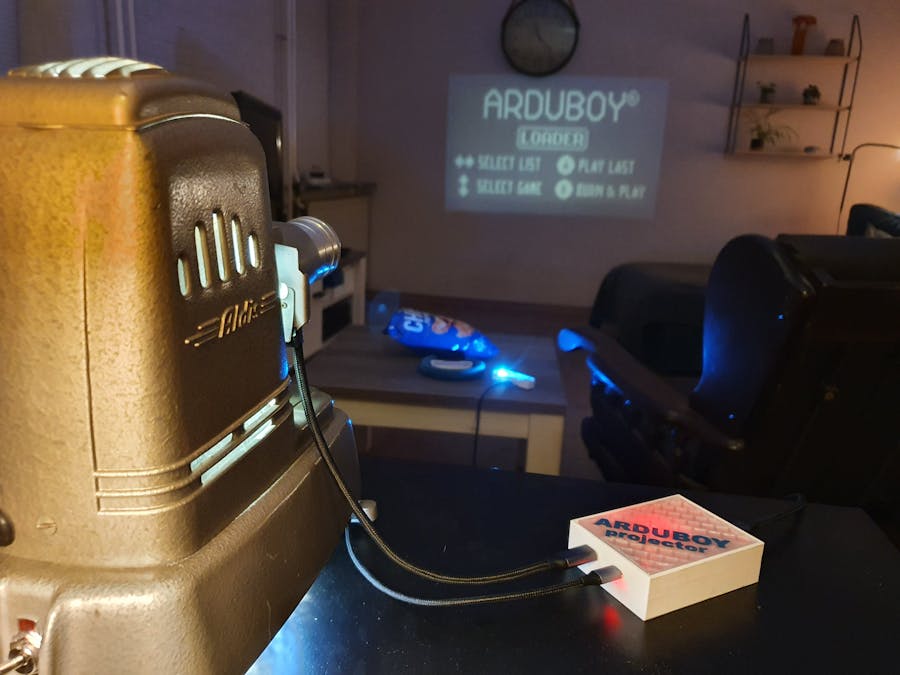
Arduboy does mix Arduino programming, with Nintendo Game Boy like handheld hardware. Screens and devices are small, so you can stick this little handheld in your pocket and take it with you everywhere. But on a Saturday evening, you like to sit back on the couch and play games on a big screen? Yes, you could buy some other Nintendo for that, but that isn't fun enough for a hack(st)er. My goal is to bring the Arduboy to a wall-sized gaming experience!
I've already build the project as a prototype version to see if it all works as expected (spoiler: yes it does).
While building the final version, I've documented all steps with pictures and video. Let me take you through the project!
History revivedAbout 15 years ago, I did purchase a projector at a flea market (Koninginnedag in The Netherlands). Why did I buy it? Because it looked pretty, as a retro item to display in my living room.
Since I'm tinkering with electronics projects based on Arduinos and Raspberry Pis, I always had a plan to do something with it. And that moment is now!
The projector is an Aldis “Aldisette 3” Slide Projector or Slide Viewer. Origin is between 1950-1960, probably built in Great Britain.
Electronics wise it is a very simple device: A power cord for 220V, a switch to turn it ON or OFF, a light bulb and a big fan to cool it. All running at 220V, no need for power conversion. The bulb didn't work anymore, and a replacement would cost me at least 7 times the price of what I paid at the flea market...
How does a projector work?A projector has four main elements, in below image from left to right:
Starting with a light source (usually fan-cooled) and a mirror to redirect light that was emitted backwards, back to the lenses.
- Starting with a light source, a very bright bulb. And a mirror to redirect light that was emitted backwards, back to the lenses.
- A pair of "condensing" lenses to direct the light in a parallel beam to the slide
- Slide with a transparent sheet with the image you want to show on screen
- A focusing or projector lens to redirect the parallel beam into an enlarging triangular beam. As you can move this lens back and forth, the image can be enlarged and focused on a perpendicular screen.
- Very often, also a flat piece of heat-absorbing glass is placed in the light path, to avoid damaging the slide. This glass transmits visible wavelengths but absorbs infrared. (not in the image)
As you can see based on the arrows, the image on the screen is flipped, compared to the image on the slide; up-side-down and left-to-right. So, you have to insert the slide upside down and backwards.
In my projector, the heat absorbing glass is between the 2 condensing lenses.
In a Projector, there is always a lot of heat from the light bulb. My Aldis projector has a large fan in the bottom to have a good air flow through the whole body.
Modernizing a 1950 projectorI have removed all old "electronics" to replace them with something safe and new.
First step is to remove the mirror as the LED I'm using is facing only one side. For heat reasons, the LED is mounted on a heat-sink, that has a little fan for airflow.
And due to the size of the light source, the LED is placed a little backwards from the first lens, compared to where the old light bulb was.
The large fan in the bottom is replaced by a 12x12 computer fan, with a light ring for fun. (I used white light, but maybe and RGB ring would have been even more fun)
The LED is working on 220V, but the fans are both running at 12V. And to power an Arduino board, I needed 5V. So, I've added a power conversion block that converts 220V to both 12V and 5V. Drawing for the box was made with Autodesk Fusion 360. As air vents, I've used the same pattern as in the fan guard that you can see in above picture.
The power cord was a bit old for my like, and the switch was even built around a piece of wood. So, these are both replaced as well.
Now I can watch slides from a long forgotten beach holiday again, hurray!
Still slides of a long-forgotten holiday, is not what I was doing this for. I want to see animations, playing games with an Arduboy. Can I “just” add a little display in a slide?
One thing to make it a little bit easier: there is no need for video playback.
Starting most modern: an OLED screen
Most of the little screens you can buy for Arduino like projects, are single color OLED screens. The Arduboy project does support many of these types of screens. Let's start with reviewing these.
The term OLED stands for Organic Light-Emitting Diodes. Very technical description: OLEDs are solid-state devices composed of thin films of organic molecules that create light with the application of electricity.
This gives us the clue we need: this is a little bit too modern. An OLED screen itself creates light, and as such it would not need a light bulb behind it. It should give enough light on its own. But that is so much light for these little screens, we cannot do this in a low-budget DIY project.
A “little” bit back in time: an LCD screen
The term LCD stands for Liquid Crystal Display. It was invented long ago (in 1888, but only commercialized around 1970), and comes in many forms, evolving from Black/"white” to full color in modern versions. Most commonly known, is the screen in your old school watch, or your high school calculator. A greenish background with black segments, forming numbers.
For a good technical description of how LCD works, see https://electronics.howstuffworks.com/lcd.htm
In short it comes down to: a layer of Liquid Crystals changes form (the crystals do twist) when you apply an electric charge to it. Due to the twist, this blocks light from passing through the layers; incoming light goes through the layers, bounces back on the mirror and due to the polarizing film, where it was blocked, you will see the segments of numbers on your calculator. If you want to see the numbers in the dark on your watch, little LEDs at the sides of the screen do light up, revealing the numbers.
For a pixel-based screen as opposed to the pre-defined numbers on the watch or calculator, a matrix of little dots is used. For standard “black-and-white", a passive matrix will work fine, although it is relatively slow.
And that is what we need here! We will use an LCD screen and remove the backlight and mirror. Our projector will be the light source.
By the way; for more details, grayscale, or even color screens and a faster refresh rate, Active Matrix or TFT screens are used. But we don't need that for a retro Projector.
On paper, that is a match!
A Passive-matrix LCD screen will suffice for a “black-and-white" image that is used by the Arduboy. Let's get building!
Bringing our projector to lifeThe screens that I've bought are "1.4 inch 128*64 COG 12864 LCD Module st7565 Controller 3.3V/5V Gray and white Backlight 8PIN 4 wires SPI interface"
This type of LCD screen is supported by the Arduboy-homemade-package from MrBlinky.
In this project description, I'll go right to taking the screen apart to proof this concept of how to use the LCD screen in a projector. If you have only one screen at hand, it might be wiser to start with first creating a working basic Arduboy to later proof your screen isn't faulty. I did buy some screens, because I probably screw up and break the glass somewhere...
Taking apart the screen
Our little screen is tightly glued on a PCB that contains just a some Resistors and Capacitors. As the flat cable between the two is very fragile, I want to keep the connection between this PCB and the screen. But as light cannot shine through the PCB, it still needs to be disconnected and put to a side.
Step 1: Start with desoldering the 2 connectors that power the backlight, and chip off the 2 plastic standoffs:
Step 2: With the screen is loose, we can remove the backlight from the actual LCD screen. Very carefully pry something between the screen and the backlight, until it comes loose.
Now the screen is the same as in above LCD technical picture: mirror at the back, layers of glass, polarizing film and Liquid Crystal in front of that.
Step 3: For this screen, the mirror and last polarizing film are glued together. There is no way to only remove the mirror in a clean way. Just go ahead removing both, we need the light to go through, and the polarizing film will be fixed later on.
Step 4: As I did already work on a prototype, I did know how to make a fitting Projector Slide like frame for the display and PCB, that fit in the projector and can keep the cabling tidy. Solder 7 cables from an USB-C 3.1 cable to the board.
Step 5: As the polarizing film is removed, how are we gonna see anything? The answer is easier than you might believe: cheap cinema Real 3D glasses! You know, these glasses you get for free (or a Euro) when you go to the cinema for a 3D movie. The idea behind Real 3D is based on polarizing glasses: both glasses have a different variation of polarization. Meaning 1 glass sees "A", the other glass sees "B". By showing A and B at the same time on screen, your eyes and brain combine that into a stereoscopic view. And that is what we interpret as 3D.
Take the glasses out of the frame and keep them in front of the display, on the side where you did remove the mirror. Notice that by turning the glasses front/back and using left/right glass, you see different results!
Note: the second option in real life looks opposite: black text, white background, but the camera apparently has some polarization filter as well?
Take the version you prefer most, cut the glasses to size and put them in the Slide frame, directly on top of your display. Now you can hold this in front of your projector and see a wall-sized presentation of whatever you are showing on screen from your Arduino!
Base Station and ControllerThe cable between the Arduino and the screen should not be too long. I did get Flash Memory issues due to voltage drop during prototype stage. So I need to keep the brains of the Arduboy close to the projector. But at the same time, I wanted to sit on the couch... Here comes an idea: I'll put the Arduino running Arduboy and the Flash memory in a Base Station. Then I'll use a long cable to connect to a Controller, that will also house the RGB LED and speaker. Clever!
Designing the Base Station
Effectively, the Base Station has only 2 components: the Arduino and the Flash Memory. There are connectors needed for power, the LCD screen and the Controller; power with USB-Micro directly into the Arduino. For the screen I need 5 wires (USB-C 3.1 had more then enough, but don't use a charging cable) and for the controller I need 12 wires (USB-C 3.1, has 13 available, again don't use a charging cable).
With Autodesk Eagle, I made a layout for a PCB to have all these on a single board.
Then with an ULP (User Language Program) called "pcb-gcode", I've created a BOTTOM ETCH and DRILL template that can be loaded into the Snapmaker Luban software. For the outline, I've manually made an additional file. When running the pcb-gcode, make sure that in Eagle in the "Selection Filter", all types are selected, and in the "Layers Filter" also ALL is selected. Generate the pcb-gcode with these settings, these worked well for me with my SnapMaker A350.
Some tricks: I've heard that the Snapmaker used to need an M5 command at the end instead of M4. I haven't tried without changing, but it worked by applying M5. Another thing is that the Snapmaker doesn't start if there are too many comment lines in the top. By turning off all comments in pcb-gcode (4th tab), ETCH works. But for DRILL you need to manually remove some additional lines at the top.
Time to load the files in Snapmaker Luban and send to the printer.
With my Snapmaker I did CNC this as a single sided PCB. The copper will be on the bottom side, as that is easiest for soldering.
For bits I've used an "End Milling Cutter 30 degree with 0.2mm tip", which gives a good and sharp trace. These bits are somewhat more expensive than a V-cutter, but for me the result was so much better! For drilling I've used an "End Milling PCB Engraving Cutter 0.8mm", which is exactly the size of a pin, but 0.9 mm is also used very often. As the last round for cutting the board outline, I've used the first bit again.
This is the first time I'm making a PCB, and following some guides, plus using the correct bits, made this a success in 2 tries (first try was in the middle of above picture, used a V-bit there).
As you see in the Eagle screenshot, there will be some bridges on the top side as I had to cross some traces. Solder them on first, using normal wires.
Then solder the components
This is all electronics we need for the Base Station. Only a nice case would make this even cooler. So there we go: Autodesk Fusion 360 again! I've used the same pattern from the fan guard on the lid of the box.
The result after printing the box, the lid and the letters:
Designing the Controller
The Controller will get all components needed "at distance of the Base Station". This will be the 4 buttons for up/down/left/right, the buttons for A/B, the RGB LED, the speaker and a reset button. The box is quite small, so no PCB this time. It could have saved me from some wire-spaghetti, but it works.
The design is based on the empty middle section of this Thingiverse design from starlightDesigns, where usually a Nintendo Switch controller is locked in place. Why such a re-design? You will see that later :)
By using an USB-C 3.1 cable, I do have 13 signal wires available, that do not blow up the controller or base station if I plugin in the cable upside down.
For the LED I need 3 wires; this became B5, D+ and D- as when you reverse the plug, these stay the same. For the speaker I used B2 and A2. If you reverse them, only the speaker is reversed without damage. For the buttons it doesn't really matter what you use. Only when you plug in upside down, the controls will be doing funny unexpected things :)
Loading code to the Base Station
Arduboy games are standalone programs. Each developer creates a full application, but by standardization of for example Pin usage (so the pin for the Blue LED is always connected to the Blue LED), games can be build platform compatible. On top of that, there are packages written to streamline the used libraries and terminology. That means there is no need for each developer to learn about writing to the display. And what if the DIY Arduboy uses another display... MrBlinky did a great job by creating the Arduboy-homemade-package, which wraps all this logic into a single library/board configuration for the Arduino IDE. As I'm not using the standard OLED screen, but an LCD screen, I have to compile each game separately. But doing so is easy!
As each game is a standalone program, you can only load one game a time. Again, MrBlinky did create the FlashCart tool for that; a method to load a bunch of compiled games into Flash Memory, and a bootloader tool that let's you select the game, and load that into the memory of the Arduino. This needs some slight different steps to first load the code. We have to create an Arduino ISP that uploads the bootloader code.
I did create a separate ISP for this, including the LED options that Arduino offers in their example ArduinoISP program.
As I'm not using the dedicated ICSP header on this programmer, in the example code, I had to change the pin assignment. The LEDs added are for Heartbeat, Error and Programming status. Upload the ArduinoISP code to this board like you upload normal Arduino code from the IDE.
Now we need to upload the bootloader. MrBlinky made some versions, I'm using the Cathy3K bootloader that starts with the menu. Connect your Programmer to the Arduboy on the ICSP header. Make sure there is no power on the USB micro! Then select the bootloader, programmer and hit Burn Bootloader:
Next is uploading you games to the Flash Memory. Here you need the FlashCart tool for. This works with Python 2.7, so first install that. Now unzip the folder you can download from the GitHub link. In the folder there is an example set of a Flash Cart. Edit the CSV file and put the correct HEX files of the compiled games in the folders. Follow the directs from the GitHub page for setting the board and display configuration. For creating a hex file, use the same settings as in above screenshot, but under Sketch, use Export Compiled Binary.
Open the Command prompt and go to the Arduboy-Python-Utilities-master folder that you downloaded. Using the standard folder structure use this command to generate the flashcart image:
python flashcart-builder.py example-flashcarts\example\flashcart-index.csvThis will show the list of games that is compiled and comments if applicable.
And then upload the image to your Arduboy:
python flashcart-writer.py example-flashcarts\example\flashcart-image.binThis will show the status, the chip that is recognized and the size of the memory. Then it will write the image to the chip.
Playing time!
That is correct, we now have all for an evening of Arduboy fun, popcorn and drinks.
Steering Wheel ControllerBut after some games, my hands and fingers feel exhausted with such a small controller. And when racing, it doesn't feel intuitive.
I want a Steering Wheel! (yes, that is why I used the starlightDesigns Thingiverse design of a steering wheel for the controller!)
The wheel is printed in 3 parts, using the version from starlightDesigns, where I did remove the bracket for the controller. Then the controller box will share the layout from the separate Controller in previous chapter.
To not change any of the Arduboy brains and existing Arduboy games, I'll externally do the logic, and then only send virtual button presses to the Base Station. That means that inside the Steering Wheel Controller, there will be an Arduino Micro and a Compass/Magnetometer. This senses if you are turning the wheel Left or Right, and if so, it magically presses the button for Left or Right.
That will be a tight fit! Also because it needs an additional reset button, and I want 2 LEDs that tell you if a Left or Right was recognized. Time for smashing all the little bits and pieces together!
And of course some coding has to be done. The idea is relatively simple:
- First do the Calibration: let the controller know what Neutral, Left and Right is.
Then we are simply running through the Loop:
- Check if the current Compass/Magnetometer position is within the range of Left/Right/Neutral, store that as CurrPos.
- Then we check if the position changed since the last run; compare LastPos with CurrPos
- If it changed, that is a button press if Left or Right; initiate the press, turn on the LED to give feedback we pressed something, and reset the counter
- If the counter is at 10, stop the button press
- If the counter is at 50, turn off the LED
- If the counter is at 100, initiate a new button press by setting the LastPos to 0, which means it is Neutral.
Doesn't sound too hard, and it was indeed not super difficult to write this. What you need, is the lsm303-arduino library from pololu. You can find this in the Arduino Library Manager by searching for lsm303. As starting point, I've used the example file for Calibration.
First import the libraries and set the global constants and parameters:
#include <Wire.h>    // Library for I2C communication
#include <LSM303.h>  // Library for the compass

LSM303 compass;
LSM303::vector<int16_t> neutral_min = {32767, 32767, 32767}, neutral_max = {-32768, -32768, -32768};
LSM303::vector<int16_t> left_min = {32767, 32767, 32767}, left_max = {-32768, -32768, -32768};
LSM303::vector<int16_t> right_min = {32767, 32767, 32767}, right_max = {-32768, -32768, -32768};
char report[80];

const byte LED_right = 9; // For testing: the RX LED has defined Arduino pin 17
const byte LED_left = 10;  // For testing: the TX LED has defined Arduino pin 30
const byte OUTPUT_right = 18;
const byte OUTPUT_left = 23;

int LastPos = 0;    // -1 = LEFT   0 = NEUTRAL   1 = RIGHT
int CurrPos = 0;    // -1 = LEFT   0 = NEUTRAL   1 = RIGHT
int LastPosTimer = 0;   // Timer for LastPos

int NrOfCalibrationSamples = 512;
int CalibrationWidening = 50;
int TimeOutForButtonReset = 10;
int TimeOutForLedReset = 50;
int TimeOutForTimerReset = 100;
Then in the SETUP() function, we will first set some basics like pin assignments and start the I2C and compass:
void setup()
{
  Serial.begin(9600);
  //while(!Serial);

  // Set the LED pins to OUTPUT
  pinMode(LED_right, OUTPUT);
  pinMode(LED_left, OUTPUT);

// Define the BUTTON pins, we do a trick :)
  // OUTPUT defaults to LOW, which is a button press
  // INPUT defaults to floating state, which is covered by the pullup on the Arduboy side
  pinMode(OUTPUT_right, INPUT);   // do not press the button anymore
  pinMode(OUTPUT_left, INPUT);   // do not press the button anymore


  Wire.begin();  // Arduino Micro default I2C pins: SDA = 2 and SCL = 3
  compass.init();
  compass.enableDefault();

  delay(200);
Next is starting calibration, we do this 3 times: NEUTRAL, LEFT and RIGHT. This is the code for NEUTRAL:
// CALIBRATE NEUTRAL

  // blink both LEDs to alert for calibration
  for (int i=0; i<=5; i++){
    digitalWrite(LED_left, HIGH);   // turn the LED on
    digitalWrite(LED_right, HIGH);   // turn the LED on
    delay(100);
    digitalWrite(LED_left, LOW);    // turn the LED off
    digitalWrite(LED_right, LOW);    // turn the LED off
    delay(100);
  }

  // Steady both LEDs while calibrating
  digitalWrite(LED_left, HIGH);   // turn the LED on
  digitalWrite(LED_right, HIGH);   // turn the LED on

  // Get standard neutral position
  for (int i=0; i <= NrOfCalibrationSamples; i++){
    compass.read();

    neutral_min.x = min(neutral_min.x, compass.m.x);
    neutral_min.y = min(neutral_min.y, compass.m.y);
    neutral_min.z = min(neutral_min.z, compass.m.z);

    neutral_max.x = max(neutral_max.x, compass.m.x);
    neutral_max.y = max(neutral_max.y, compass.m.y);
    neutral_max.z = max(neutral_max.z, compass.m.z);

    delay(10);
  }

  // Off for both LEDs as calibration is complete
  digitalWrite(LED_left, LOW);    // turn the LED off
  digitalWrite(LED_right, LOW);    // turn the LED off

  // Update the readings with a little extra range
  neutral_min.x = neutral_min.x - CalibrationWidening;
  neutral_min.y = neutral_min.y - CalibrationWidening;
  neutral_min.z = neutral_min.z - CalibrationWidening;
  neutral_max.x = neutral_max.x + CalibrationWidening;
  neutral_max.y = neutral_max.y + CalibrationWidening;
  neutral_max.z = neutral_max.z + CalibrationWidening;

  snprintf(report, sizeof(report), "NEUTRAL = min: {%+6d, %+6d, %+6d}    max: {%+6d, %+6d, %+6d}",
    neutral_min.x, neutral_min.y, neutral_min.z,
    neutral_max.x, neutral_max.y, neutral_max.z);
  Serial.println(report);

  delay(300);
Once calibration is done, the SETUP() is complete. Now we go into the actual program with the LOOP() function:
void loop()
{
  compass.read();  // Read the compass data

  // Find if the compass Magnetometer is in one of our direction ranges
  if( compass.m.x > right_min.x && compass.m.x < right_max.x &&
      compass.m.y > right_min.y && compass.m.y < right_max.y &&
      compass.m.z > right_min.z && compass.m.z < right_max.z ) {
      CurrPos = 1;
    }
  else if( compass.m.x > left_min.x && compass.m.x < left_max.x &&
      compass.m.y > left_min.y && compass.m.y < left_max.y &&
      compass.m.z > left_min.z && compass.m.z < left_max.z ) {
      CurrPos = -1;
    }
  else if( compass.m.x > neutral_min.x && compass.m.x < neutral_max.x &&
      compass.m.y > neutral_min.y && compass.m.y < neutral_max.y &&
      compass.m.z > neutral_min.z && compass.m.z < neutral_max.z ) {
      CurrPos = 0;
    }

  // Find if the last position is different from current position. If yes, turn on the LED and virtually press the button
  if ( LastPos != CurrPos) {
      digitalWrite(LED_right, LOW);   // turn the LED off
      digitalWrite(LED_left, LOW);   // turn the LED off
      pinMode(OUTPUT_right, INPUT);   // do not press the button anymore
      pinMode(OUTPUT_left, INPUT);   // do not press the button anymore

      if (CurrPos == -1) {
          Serial.println("LEFT");
          digitalWrite(LED_left, HIGH);   // turn the LED on
          pinMode(OUTPUT_left, OUTPUT);   // press the button
        }
      if (CurrPos == 1) {
          Serial.println("RIGHT");
          digitalWrite(LED_right, HIGH);   // turn the LED on
          pinMode(OUTPUT_right, OUTPUT);   // press the button
        }
      LastPos = CurrPos;  // Position to LEFT or RIGHT
      LastPosTimer = 0;  // Reset timer to 0
    }

  // If in the same direction, loop for turning the press off, turning the LED off, and turning back to neutral
  else {
    if (LastPosTimer == TimeOutForButtonReset && CurrPos == -1) {
        pinMode(OUTPUT_left, INPUT);   // do not press the button anymore
      }
    if (LastPosTimer == TimeOutForButtonReset && CurrPos == 1) {
        pinMode(OUTPUT_right, INPUT);   // do not press the button anymore
      }

    if (LastPosTimer == TimeOutForLedReset && CurrPos == -1) {
        digitalWrite(LED_left, LOW);   // turn the LED off
      }
    if (LastPosTimer == TimeOutForLedReset && CurrPos == 1) {
        digitalWrite(LED_right, LOW);   // turn the LED off
      }

    if (LastPosTimer == TimeOutForTimerReset) {
        LastPosTimer = 0;  // Reset timer to 0
        LastPos = 0;   // Position to NEUTRAL, such that it triggers next time
      }
    else {
        LastPosTimer++;  // Add 1 to timer
      }
  }

  delay(10);  // Next loop in 10 ms
}
That's all we need for the Arduino inside the Steering Wheel Controller.
Upload the code, close the lid, start the projector and GAME ON!
When I plug in the controller, first 2 orange lights show up, this is the calibration for Neutral position. Hold the wheel upwards and move gently to give it some points for recognizing the upward position. Then the left light shows; calibration for Left, move to the left and gently move around again. And lastly right light, you could guess it, calibration for Right. After the calibration, the controller will send the virtual button presses when a left or right move is detected.


_t9PF3orMPd.png?auto=compress%2Cformat&w=40&h=40&fit=fillmax&bg=fff&dpr=2)


Comments