


Hardware components | ||||||
| × | 1 | ||||
| × | 1 | ||||
| × | 1 | ||||
| × | 8 | ||||
 |
| × | 1 | |||
| × | 1 | ||||
Software apps and online services | ||||||
 |
| |||||
Or keep on spinning your DC motor forward and backward
IntroductionThis note illustrates the introductory use of a very simple motor with minimal commands from an Arduino single board microcomputer. Since understanding this operation is the most fundamental step towards using all kinds of motors with microcomputers, a few extra paragraphs have been included in the article to enable you to ramp up the learning curve as quickly as practical.
StoryThere are three basic types of motors used with single board computers:
• Direct Current (DC)
• Servo
• Stepper
This note is limited to a simple (and single) DC motor. The use of the other two types of motors as well as advanced configurations of DC motors will be illustrated in future articles in due course.
Direct Current MotorThe rotation of the DC motor arises from the application of electrical energy to the device. For the limited purposes of this note, the form of electrical energy to the DC motor, as the name implies, is direct current. A key characteristic of these types of motors is that reversal of polarity of the DC feed to the motor results in a reversal of the rotation as shown in the figure below:
The figure illustrates a very simple circuit with four switches. The three states of the DC motor are:
• Stop
• Rotate
• Counter Rotate
Stop
When all four switches are set to the OFF condition then there is no power to the DC motor. The tautological assertion is that in the absence of electrical power to the motor there is no rotation.
Rotate
When only two diagonally opposite switches (as illustrated in the above figure) are in the ON condition, the motor will rotate. The direction of rotation follows Fleming’s left hand rule (see reference below).
Counter Rotate
When the opposite set of switches are in the ON condition (and the other two are OFF), the motor will rotate in a direction counter to that described in the previous section.
Hobby DC MotorsA hobby DC motor provides the basic introduction
The nominal specifications of these motors, on average, are shown below in the table:
Pulse Width ModulationThe most elementary way to control the rotational speed of a DC motor is to adjust the voltage to the motor using a potentiometer. Unfortunately, this arrangement is inefficient and it wastes energy.
The use of digital modulation technique to provide an average voltage is more efficient since the power loss is very low. When it is off there is practically no current. When it is on and power is being transferred to the load, there is almost no voltage drop across the switch. Thus, power loss (as measured by Watts = Voltage * Current) is close to zero.
One variation of this technique, known as Pulse Width Modulation (PWM), is shown below:
The pins on the Arduino board that support PWM have the tilde character, “~”, as a prefix. The pins are 3, 5, 6, 9, 10, and 11. The method, analogWrite, is available to write to the pin as follows:
Controlling the MotorThe Arduino UNO R3 board has the following limitations for the flow of current:
• Under USB power: 500 mA (protected by polyfuse but bypasses onboard 5 V voltage regulators)
• Under external power (barrel connector): 500 mA – 1 A
If both connections are used then the power from the barrel connector is preferred as long as the voltage is above 6.6 V DC.
A typical hobby DC motor has the following requirements for the flow of current:
• Starting voltage: 2 V DC
• Rated voltage: 6 V DC
• Stall current: 800 mA
Owing to these differences Therefore in practice to assist the Arduino to drive the motor an electronic interface is desirable. The added advantage of this interface is that it supports bi-directional rotation control of the motor without extraneous switches. One such interface is the L293 integrated circuit (IC) chip.
L293D ChipThe L293D chip, shown below, can control two motors with current rated at 1 A thereby enabling the Arduino board to issue commands for the rotation and stoppage of the motors.
The chip circuit is a simple H-bridge as shown below for a single motor:
L293D pin Reference Description Arduino pin
The state of the motor (only the 1st motor connection for this exercise) is controlled using the following table:
EN1 IN1 IN2 Motor State
HIGH LOW HIGH Turn right
HIGH HIGH LOW Turn left
HIGH LOW LOW Stop
HIGH HIGH HIGH Stop
LOW HIGH or LOW HIGH or LOW Stop
The three test cases for the exercise can be reduced to the following functions:
• Stop
• Rotate
• Counter rotate
All references are to the first (and only) motor in the assembly.
StopSet the corresponding pin to stop the motor as follows:
• EN1 to LOW
The code snippet for the stop function is as follows:
// several methods to stop the motor; this one is the simplest
void motorStop(byte motorNumber)
{
 digitalWrite(weepins[motorNumber][0], LOW);     // free-running motor stop; state of A pins do not matter
}
Set the corresponding pins to rotate the motor as follows:
• EN1 to HIGH
• IN1 to LOW
• IN2 to HIGH
The code snippet for the rotate function is as follows:
// the direction of rotation depends on the pin connections to the motor
void rotate(byte motorNumber, byte motorSpeed)
{
 digitalWrite(weepins[motorNumber][0],HIGH);   // turn right - depends on motor polarity
 digitalWrite(weepins[motorNumber][1], HIGH);  // per L293D truth table
 digitalWrite(weepins[motorNumber][2], LOW);
 analogWrite(weepins[motorNumber][0], motorSpeed);
}
Set the corresponding pins to counter rotate the motor as follows:
• EN1 to HIGH
• IN1 to HIGH
• IN2 to LOW
The code snippet for the counter-rotate function is as follows:
// the direction of rotation depends on the pin connections to the motor
void counterRotate(byte motorNumber, byte motorSpeed)
{
 digitalWrite(weepins[motorNumber][0],HIGH);       // turn left - depends on motor polarity
 digitalWrite(weepins[motorNumber][1], LOW);        // per L293D truth table
 digitalWrite(weepins[motorNumber][2],HIGH);
 analogWrite(weepins[motorNumber][0], motorSpeed);
}
There are many efficient ways to program the instructions for these operations especially when more than one motor is in use. However, for the limited purposes of this test exercise, these techniques are beyond the current scope and the approach commonly referred to as brute-force is illustrated.
The three functions are tested in the sample code in the following sequence:
• rotate (iterate the PWM value from 1 to 255)
• stop
• counter-rotate (iterate the PWM value from 1 to 255)
• stop
It may instructive to have a longer delay between the increments of the PWM value if external measurements are planned.
Hardware ComponentsDocumenting the BuildAll projects in this introductory set of basic and elementary projects, the microcomputer board and the breadboard are mounted on a base-plate. This technique has been illustrated in a previous project and for the sake of brevity will not be repeated here.
The final assembly is shown below:
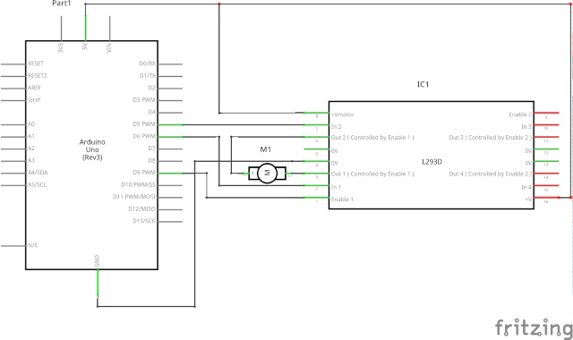
The diagram below illustrates the schematic for the elementary exercise to test the hobby DC motor:
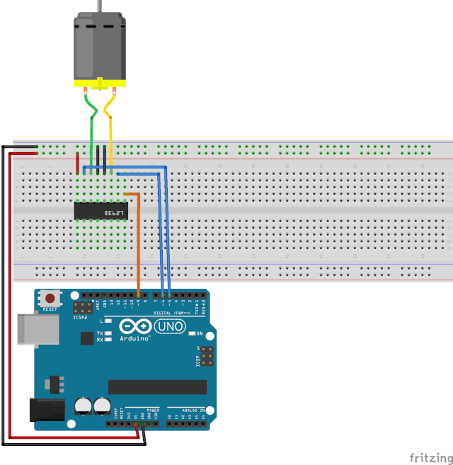
The assembly diagram below illustrates a proposed layout for the exercise:


Comments