


Purpose:
To act as a desk and project lamp, where the color temperature can be adjusted ranging from a very cool white, to very warm white, and the brightness can be varied. It will be controlled by an Espruino ( www.espruino.com ) board, and capable of loading “preset” colors, as well as adjusting the color channels individually.
I decided to use 1 and 3W luxeon clones (commonly called LED beads) for the lighting, in 5 channels. All LEDs used are phosphor based, even the yellow.
Additionally, the controller will monitor environmental conditions, and provide readout, including a graph of the past 24 hours on the backlit LCD screen. Time and sensor readings will also be displayed on a connected Nixie tube display (using SmartNixie tubes from switchmodedesign.com).
The controller will be connected to the network, and can be controlled remotely over the network, and, in turn, can control the relays in a Fargo ( www.linortek.com ) unit over the network.
Hardware:
The hardware can be broken down into 5 parts:
The Arm: The first problem was to obtain an articulating arm that can clamp to the table and hold the light head in the desired location. Luckily, I had vintage-1960’s flourescent desk lamp, which I gutted, and removed the head from, and then ran 6-conductor wire down it. Tricky wire running job, as there are also springs and straps inside the arm. The base of the arm has sufficient space for the MOSFETs and and resistors, and a terminal strip at the back (removable) for easy maintenance.
The Head: The LEDs must be mounted on a heatsink to avoid burning out. The heatsink used here was about 4”x3.5”, obtained from one of the audio amplifiers from an old projection screen TV (these are readily available for free on classifieds/freecycle/craigslist, at least in the US - worth scrapping for the huge fresnel lens, trapazoidal (often front surface) mirror, speakers (sell on ebay), and some heatsinks).
I soldered the positive side of all the LEDs together, and thermal-epoxied them to the heatsink. This way sucked, and I recommend epoxying all the LEDs down in the right pattern first, and then connecting to them. And being more careful so the frame isn't at +5 volts. For running the 1W and 3W white LEDs off the same voltage, a 0.68 ohm resistor was necessary in series with the 1W LEDs.
Version2 note:
In version 2 of the head, the 14 LEDs (after straightening the leads with pliers) were epoxied to the heatsink first, and then connected, which ensured much better thermal contact between the LED and heatsink. As before, the positive wires were connected together. The LEDs themselves were connected in series - 2 Cold White 3W, 2 Warm White 3W, 3 Ice Blue 1W, 2 yellow 1W + 1 610nm orange 1W, 2 630nm red 5W dual die + 2 660nm deep red 3W dual die.
The heatsink is screwed onto the backing plate (which is in turn affixed to the arm using the same mount that was used for the original lighting head). To allow the head to be removed for maintenance, the LEDs are connected to a pair of 3 wire terminal strips on the head backing plate. Finally, the shroud is affixed using 4 screws (not installed in above picture).
The diffuser is made with 2 pieces of diffuser, as is used in flourescent lights suspended from ceilings (the style is common in schools and office buildings), cut to size such that they can be wedged in place.
LED drivers: The ballast resistors and MOSFET driver board are located in the base of the arm. The ballast resistor values are low (1.3, 2.8 and 3 ohms), and have to be picked fairly close to the targeted value to get full brightness from all channels without exceeding the manufacturers’ specifications.
The board itself was prepared from single-sided copper-clad board from Amazon, using the Toner Transfer method. Design and layout was done in Eagle.
The MOSFETs are DMN2075-U's, rated for 4.2A continuous at 2.5v on the gate.
Version 2 note:
In version 2, the drivers are AMC7140 linear constant current regulators - see build log for phoros.
Nixie Display: A 6-tube nixie display provides time and sensor readout. The display consists of 6 SmartNixie devices in the laser cut case from the kickstarter campaign. The last tube has an IN-19 symbol tube in it, with % and deg. C symbols. The SmartNixie tubes are controlled by a single serial line.
Controller: The controller consists of an Espruino Board 1.3, a 5x4 keypad for control, 128x64 3.2" black and white digole display, backlight, DHT22 and BMP180 sensors, a WIZ5500io network adapter, a buck converter, and a power distribution board, all crammed into an overturned plastic storage bin.
The display has been modified by carefully removing the rear reflective layer, and mounting it on top of an appropriately sized piece of EL Panel. Cleanly removing the sticky crap under the reflective layer was difficult, as you cannot scrape without damaging the polarizing filter behind it. I used q-tips, rubbing alcohol, fingernails, and patience. Then, to make it look nice, I edged it in black electrical tape, to block light from showing through outside the active area of the display. It is driven by the Digole smart LCD controller, which is in turn controlled over I2C. The backlight uses an inverter meant to run on 2 alkaline batteries, running off the 3.3v supply.
The sensors are all tied together one one board, with DHT22, BMP180, and an I2C EEPROM, as well as an I2C tap to connect to the display. This is sub-optimal. I intend to move the DHT22 and BMP180 outside of the case, to keep the heat from the electronics from throwing off the readings. The EEPROM is used to store the desk light presets.
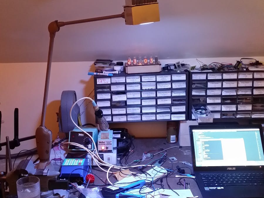
Power is supplied at ~12v from the power supply running my Fargo. In the pictures, the white box that the soldering irons are sitting on contains the Fargo and 12v supply. This is used to power the Nixie display, and is fed to a cheap buck converter to provide 5.6v for the LEDs. The Espruino is run off this 5.6V as well. A power distribution board acts as a splitter to connect all the components to power; this board contains a 3.3v regulator to provide 3.3v to power-hungry devices like the Network adapter and backlight.
The buck converter is at the edge of it's capabilities when all the LEDs are on; it's not sized appropriately, but the next size up was much larger, and I wouldn't have been able to fit everything. I added heatsinks on the buck converter driver, as well as the board on the opposite side.
Version 2 changes:
DHT22 is now located outside of case. I plan to put a P-channel MOSFET on the input, so that I can reset it; it seems that the DHT22 sometimes gets unhappy, and won't give valid readings until it is power-cycled.
BMP180 is disconnected while I investigate why it works consistently on the bench, just as consistently as it never works inside the desklamp.
2 EEPROMs are used on I2C2 - a 512kbit one on 0x51, for use for storing snippets of code to save memory, and a 4-kbit (512 byte) FRAM module. The FRAM has no delay on write, and a effectively unlimited rewrites. This is used to store the rolling temperature/humidity/pressure history, which is fully rewritten every 30 minutes.
Software:
Everything is controlled using the Espruino Board. This code is up against the memory limits, and will only work if minification is enabled. When the Espruino Pico board becomes available in April, I may switch to using that, for the smaller footprint and greater memory capacity.
I don't feel like much of what was done in the code is particularly noteworthy, though I think a few bits are worth mentioning:
I add several new functions to 'g', the graphics object for the LCD, to perform simple operations using the hardware commands on the digole display, instead of just redrawing the whole thing. This is much faster for these operations, and signifiantly improves the user experience. Most of the time savings comes from reduced calls to E.reverseByte(). I control whether to do this in uplcd, which takes an argument from what it's called from that determines how much of a redraw is needed.
The T9xxx methods are to assist with text entry - it doesn't actually do T9 (with the looking up words in dictionary) - instead it's like how you entered text on a cellphone before T9, where pressing the button cycled through the available letters and the number associated with that key, and pressing a different number, or pausing for a bit will commit that letter and move the cursor to the next char.


Comments