

Hardware components | ||||||
 |
| × | 1 | |||
 |
| × | 1 | |||
 |
| × | 1 | |||
 |
| × | 1 | |||
 |
| × | 1 | |||
Software apps and online services | ||||||
 |
| |||||
 |
| |||||
The system is implemented on an embedded platform & is equipped with a photo sensitive detector (LDR) which gives the required input for operation.The working of our light control system is based on the amount of luminous energy in the environment at that moment of time. Depending upon the light intensity at that instant the lighting of the lighting system is adjusted. The embedded main Bolt board including the Microcontroller chip, memory (flash), and communication port are used as a processing module for the input that we get from peripheral devices (LDR).
ARCHITECHTURE DIAGRAMCIRCUIT COMPONENTS:
1. LIGHT DEPENDENT RESISTOR(LDR) SENSOR
Light Dependent Resistor as the name suggest the resistance is dependent upon the light incident on it. The light dependent resistor resistance changes with intensity of light, with increase in light intensity the resistance offered by the sensor decreases and with decrease in light intensity the resistance offered by the sensor increases. Hence it act as variable resistor with change un light intensity.
2.Bolt Wifi Module
The embedded main Bolt Wifi Module board including the Microcontroller chip, memory (flash), and communication port are used as a processing module for the input that we get from peripheral devices (LDR).
A light-emitting diode (LED) is a pn junction diode, which emits light when activated. When we apply voltage across its leads, electrons are able to recombine with holes within the LED, releasing energy in the form of photons which gives the Light.
WORKING of the PROJECT1) The LDR sensor keeps reading the value of the light intensity of a place.
2) The maximum value the sensor can read is 1024. Which means that the lights are ON.
3) So you can set the max_value to about 800 to make sure that the BOLT module respond by sending you an SMS using Twilio that the lights are ON.
4) If the lights are OFF it does the same thing. The minimum_limit can be set according to your will. so you can set the min_value to about 500.
5) So if the sensor value becomes less then 500 it will again inform you by sending you an SMS that that the lights are OFF.
6) If the lights are OFF it automatically turn ON the lights (In this case I used the LEDS to show the working ).
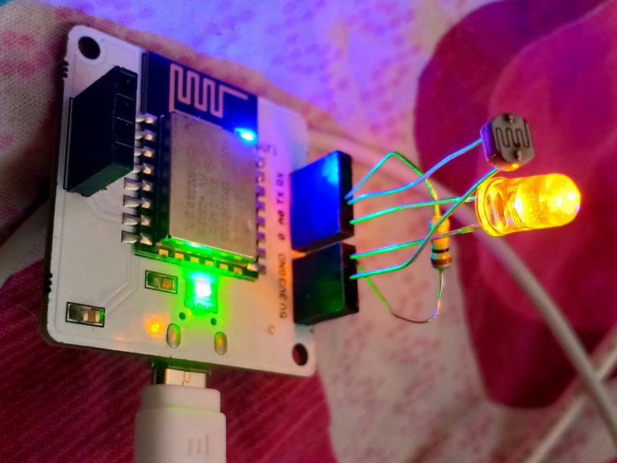
CIRCUIT CONNECTION:1) Insert negative pin of LED into the ground pin of the bolt
2)Insert positive pin of LED into the '0' pin of the bolt
3)Insert one lead of the LDR into the Bolt Module's 3v3 Pin.
4)Insert other lead of the LDR into the A0 pin
5)Insert one leg of the 10k Ohm resistor into the GND pin
6)Insert the other leg of the resistor also into the A0 pin
7)connect Bolt Wifi Module to the power supply using usb cable
Step 1: Open https://www.twilio.com/ in browser.
Step 2: Click on Get a Free API Key button to sign up.
Step 3: Fill all the necessary details in SIGN UP form. Below is the screenshot of filled sign up form.
Step 4: To verify they will ask for your phone number. Choose India as an option in the dropdown and then enter your phone number.
Step 5: Click on "Products" as shown on the screen below,
Step 6: Now enable the SMS services by clicking on two checkboxes for Programmable SMS and Phone Numbers as shown below.
Step 7: Now, you will need to give a name for your project. I have given the name as My Project. Click on "Continue" once you have entered the project name.
Step 8: Click on "Skip this step" when it asks you to Invite a Teammate.
Step 9: Your project should be created at this point. Click on "Project Info" to view the account credentials which is required for your projects.
Step 10: You can view the Account SID and Auth token on this page. The Auth token is not visible by default, you can click on "view" button to make the Auth token visible as shown below. Copy both and save them somewhere securely.
Step 11: From the drop-down menu, choose "Programmable SMS". Now click on Get Started button to generate phone number.
Step 12: Click on Get a number button.
Step 13: Then a popup will appear. Click on Choose this number button
Step 14: Then a popup will appear which will have the final number. Copy this number and save to notepad for future references.
That's it. You have successfully created the account on Twilio. In the next lesson, we will use Bolt Python library to create our own SMS Alert system..
ALERT notification on mobile(example)The python coding for this project has been done in Ubuntu (Linux). Before we start coding of the automating controlling of LED brightness in python, we need to make a configuration file which will have the specific keys for each user/device. We will import this file in our main code and use the various attributes. The advantage of this is that each user will only have to change the contents the configuration file to use the product.
SID = 'You can find SID in your Twilio Dashboard'
AUTH_TOKEN = 'You can find  on your Twilio Dashboard'
FROM_NUMBER = 'This is the no. generated by Twilio. You can find this on twilio dashboard'
TO_NUMBER = 'This is your number. Make sure you are adding +91 in beginning'
API_KEY = 'This is your Bolt Cloud accout API key'
DEVICE_ID = 'This is the ID of your Bolt device'


Comments