


Hardware components | ||||||
 |
| × | 1 | |||
 |
| × | 1 | |||
| × | 1 | ||||
| × | 4 | ||||
| × | 4 | ||||
| × | 1 | ||||
Software apps and online services | ||||||
 |
| |||||
Hand tools and fabrication machines | ||||||
 |
| |||||
 |
| |||||
‘Sumo 3K - A WiFi-Controlled 4WD Combat Robot’ was built to participate in a Robotics competition. The objective - design, build, and programme an autonomous WiFi-controlled combat robot weighing no more than 3 kg, capable of outmanoeuvring and overpowering opposing robots in a circular arena of 1 - 1.5 metres diameter.
- ‘Sumo 3K - A WiFi-Controlled 4WD Combat Robot’ was built to participate in a Robotics competition. The objective - design, build, and programme an autonomous WiFi-controlled combat robot weighing no more than 3 kg, capable of outmanoeuvring and overpowering opposing robots in a circular arena of 1 - 1.5 metres diameter.
- Two physics concepts are central to the engineering design decisions:
- Friction: The force required to push the opposing robot is resisted by static friction. Maximising the normal force (i.e., weight) and the coefficient of friction (tyre material) increases the robot's grip on the arena floor. High-tread rubber tyres were selected for their high coefficient of friction. A significant learning during testing was the observable difference between static and dynamic friction. When the battery voltage dropped, and the robot's weight increased upon fitting the top chassis, the robot required an initial push, demonstrating that static friction (the force needed to initiate movement) exceeds kinetic friction (the force during motion).
- Torque: Motor torque is the rotational force transmitted to the wheels. DC Johnson motors at 12V / 500 RPM were selected because they produce high torque at the chosen operating voltage, translating to greater pushing force. A 4WD configuration was chosen over 2WD to distribute torque across all four wheels, maximising traction and reducing the likelihood of wheel-spin under load.
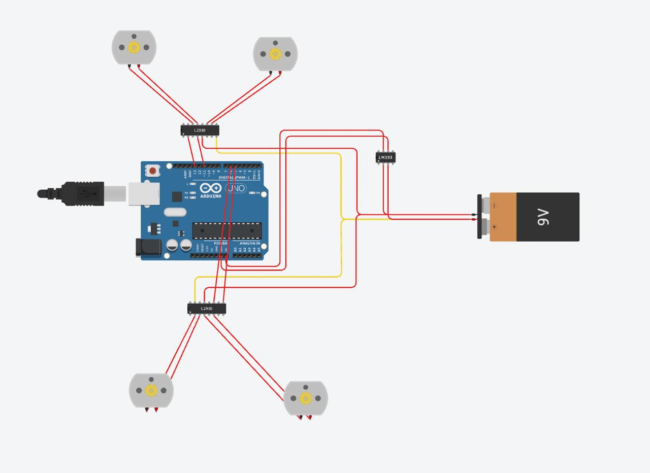
- Two motor driver architectures were evaluated:
- BTS7960 43A H-Bridge: A high-current driver well-suited to large motors. However, the associated step-down transformer delivered unstable voltage, causing two ESP32 microcontrollers to fuse (overvoltage failure). This circuit was abandoned.
Circuit Diagram - Considered
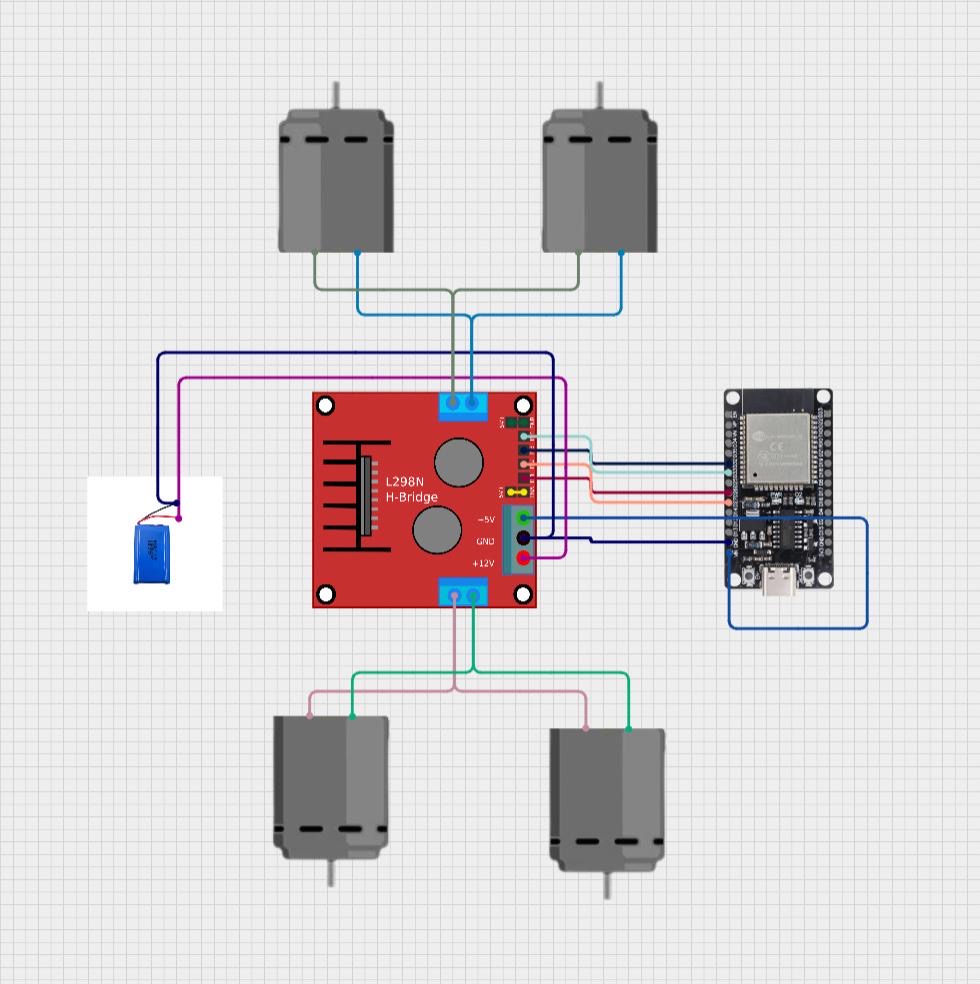
- L298N H-Bridge with onboard 5V regulation: The L298N's integrated voltage regulator eliminated the need for a separate step-down converter, dramatically simplifying the circuit and resolving the overvoltage problem. This became the final design.
Circuit Diagram - Final
- Chassis Approach: 3D-Printed Plastic Chassis, Aluminium Extrusion Frame, and Laser-Cut Metal Sheet chassis designs were considered. Laser-Cut Metal Sheet Chassis was chosen for its high rigidity, heavy natural ballast, moderate cost, the possibility of custom shapes, and the availability of local fabricating & welding facilities. It was fabricated externally, and external welding was needed to fix motor holders onto the chassis.
- Chassis Fabrication: A metal sheet was laser-cut to a custom shape that balanced surface area, weight distribution, and wheel placement. The design included slots for cable routing and mounting holes for all components. Motor holders were subsequently welded onto the four corners of the base chassis. A matching top plate was fabricated to enclose the electronics.
- Mechanical Assembly was performed in stages
- Stage 1: Chassis base and cover fabricated
Chassis - base & cover
- Stage 2: Motor holders welded to the chassis base
Chassis - motor holders welded
- Stage 3: Four DC Johnson motors mounted to the welded holders
Chassis - motors mounted
- Stage 4: High-friction rubber tyres fitted to all four motor shafts
Chassis - wheels fitted in
- Stage 5: 7.4V 18650 Lithium-Ion battery (4000 mAh) secured to chassis with zip ties
- Stage 6: L298N motor driver module positioned and mounted
Chassis - battery and motor driver fitted in
- Stage 7: ESP32 microcontroller installed
Chassis - microcontroller fitted in
- Stage 8: Top chassis plate fitted and secured to complete the enclosure
Sumo Robot - all fitted in
- Electronics — Wiring and Circuit - The final circuit connected the following components:
- Battery to Motor Driver:
- Battery +ve → L298N 12V input
- Battery –ve → L298N Ground
- Motor Driver to ESP32:
- L298N IN1 → ESP32 GPIO26
- L298N IN2 → ESP32 GPIO27
- L298N IN3 → ESP32 GPIO32
- L298N IN4 → ESP32 GPIO33
- L298N 5V (onboard regulator output) → ESP32 VIN
- L298N GND → ESP32 GND
- Motor Connections:
- Front-left and front-right motors connected to L298N Output A channels
- Rear-left and rear-right motors connected to L298N Output B channels
- All connections were made using colour-coded wires and soldered at the motor terminals. The L298N's integrated 5V regulator powered the ESP32 directly, eliminating the voltage instability that caused failures in the original BTS7960 circuit.
Circuit Diagram - Final
- Software — WiFi Control System
- Code was written in C++ using the Arduino IDE and uploaded to the ESP32 via Micro USB
- The ESP32 was configured as a WiFi access point, hosting a web server accessible via a smartphone browser
- The web interface displayed directional controls (Forward, Backward, Left, Right, Stop) rendered as a D-pad layout
- HTTP GET requests from the browser triggered GPIO signal changes that commanded the L298N to drive the respective motor pairs
- The complete source code is available at: https://github.com/AvyuktChhabra/Sumo-3KG
Mobile Control for Sumo 3K
- During integrated testing after the top chassis plate was fitted, the robot failed to begin moving from a standstill. It required a small manual push to initiate motion. Diagnosis revealed two contributing factors:
- The battery voltage had depleted slightly during the extended development period, reducing motor drive current; and
- The added weight of the top chassis plate increased the normal force and, therefore, the static friction that the motors needed to overcome at start.
- Resolution: Recharging the battery restored sufficient motor current. This episode provided a direct, experimentally observed confirmation that the coefficient of static friction (μs) is greater than the coefficient of kinetic friction (μk) — a fundamental principle of Physics. The robot would not begin moving until the applied motor force exceeded μs × mg; once in motion, it continued smoothly because the kinetic friction was lower.
- Functional Testing - Following the circuit redesign and battery recharge, all motion commands (forward, backward, left turn, right turn, stop) were tested and confirmed functional. Three working videos were recorded to document performance:
- Look & Feel:
- Forward motion:
- Backward motion:
- The completed robot weighed 2.35 kg, verified by a digital scale, satisfying the 3 kg competition limit and leaving 650 g of headroom for future enhancements, e.g., a servo-actuated lever mechanism.
Weight - Without Sumo 3K
Weight - With Sumo 3K (difference 2.35 Kg)
- Engineering Analysis: The project successfully demonstrates the application of core physics and electronics principles in a real-world engineering context:
- Mechanical advantage through torque: The 12V / 500 RPM DC Johnson motors were selected because higher torque at lower speed is more effective for pushing applications than high-speed, low-torque alternatives. Torque (τ = F × r) is the product of force and the wheel radius; the motors provide the rotational force, and the gearing within the motor maintains adequate output torque at the wheel.
- Friction optimisation: The choice of high-tread rubber tyres directly maximised the coefficient of friction (μ) at the wheel-floor interface. The pushing force the robot can exert on an opponent is limited by the lesser of: (a) the motor output force, and (b) the maximum static friction force (f = μ × N = μ × mg). With four wheels each contributing independently, the total traction force is effectively quadrupled compared to a single-wheel drive.
- Electronics reliability: The BTS7960-to-L298N redesign illustrates the engineering tradeoff between component performance and circuit reliability. Although the BTS7960 can theoretically handle higher currents, the associated power supply instability made it unsuitable for this application. The L298N's integrated regulation trading theoretical headroom for real-world stability was the correct engineering decision.


2 projects • 0 followers
I am an IB DP student with a strong passion for engineering, physics, and robotics. I am a Robotics enthusiast and a Maker-Builder.
Thanks to Amartya Jha.


_3u05Tpwasz.png?auto=compress%2Cformat&w=40&h=40&fit=fillmax&bg=fff&dpr=2)
Comments