

Hardware components | ||||||
| × | 1 | ||||
 |
| × | 1 | |||
| × | 1 | ||||
| × | 1 | ||||
 |
| × | 1 | |||
Audio technology has undergone remarkable evolution in recent decades, reshaping how we consume digital media. From classic tube amplifiers to modern media players, technological advancements have significantly altered the landscape. Portable media players, in particular, have garnered immense popularity due to their vibrant sound quality and extended battery life.
As an electronics enthusiast, I often ponder how these devices achieve such impressive audio quality. While speaker technology advancements are noteworthy, the pivotal factor lies in amplifier advancements, particularly in Class D amplifiers. In this project, we'll delve into the workings of Class D amplifiers, exploring their strengths and weaknesses. Furthermore, we'll embark on the exciting task of constructing a hardware prototype of the amplifier to assess its performance. It promises to be an engaging journey, so let's dive in and get started!
Basic knowledge of Class D amplifiersWhat is a Class D audio amplifier? The simplest answer is that it's a switching amplifier. But in order to understand how it works, we need to understand its functionality and how the switching signal is generated, for which you can follow the block diagram given below.
So why use a switching amplifier? The obvious answer to this question is efficiency. Class D audio amplifiers can be as efficient as 90-95% compared to Class A, Class B, and Class AB amplifiers. Class AB amplifiers have a maximum efficiency of 60-65% because they operate in the active region and exhibit low power losses, which you will find if you multiply the collector-emitter voltage by the current. To learn more about this topic, check out our article on the power amplifier category, where we discuss all relevant loss factors.
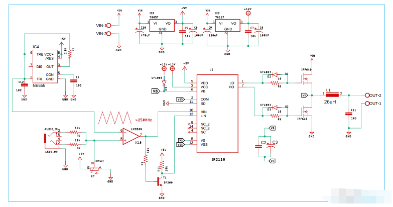
Now, going back to the simplified block diagram of our Class D audio amplifier, as you can see on the non-inverting side we have the audio input and on the inverting side we have the high frequency triangle signal. At this time, when the voltage of the input audio signal is greater than the voltage of the triangle wave, the output of the comparator becomes high level, and when the signal is low level, the output is low level.
With this setup, we just modulate the input audio signal with a high frequency carrier signal and then connect it to the MOSFET gate driver IC, as the name suggests, the driver is used to drive the gate side and low side of both MOSFETs at once. At the output we get a strong high frequency square wave at the output which we pass through a low pass filter stage to get our final audio signal.
Components required to build a Class D audio amplifier circuitNow that we understand the basics of Class D audio amplifiers, we can start looking for components to build a DIY Class D amplifier. Since this is a simple test project, the component requirements are very general and you can find most of them at your local hobby shop. A list of components with pictures is given below.
Parts list for building a Class D power amplifier:
IR2110 integrated circuit - 1
Lm358 Op Amp - 1
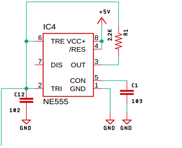
NE555 timer IC - 1
LM7812 integrated circuit - 1
LM7805 integrated circuit - 1
102 pF capacitor - 1
103 pF capacitor - 1
104 pF capacitor - 2
105 pF capacitor - 1
224 pF capacitor - 1
22uF capacitor - 1
470uF capacitor - 1
220uF capacitor - 1
100uF capacitor - 2
2.2K resistor - 1
10K resistor - 2
10R resistor - 2
3.5mm audio jack - 1
5.08 mm screw terminal - 2
UF4007 Diode - 3
IRF640 MOSFET - 2
10K Decorative Pot - 1
26uH inductor - 1
3.5mm headphone jack - 1
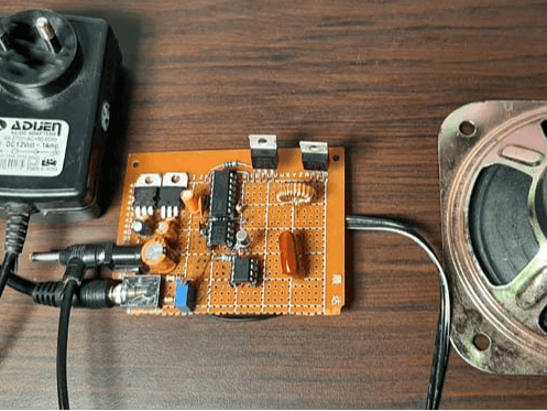
Building a circuit on PerfBoardAs you can see from the main picture, we made the circuit on a piece of perfboard. Because, firstly the circuit is very simple and secondly if something goes wrong we can modify it quickly and easily. We made most of the connections with the help of copper wires, but at some final stages we had to use some connecting wires to complete the build. The completed perforated board circuit is shown below.
In the setup depicted in the image, a 12V power adapter is employed to energize the circuit. Interestingly, the adapter, sourced from an affordable Chinese product, delivers a slightly higher voltage of 13.5V, conveniently matching the requirements of our onboard LM7812 voltage regulator. The load used in this configuration is a 4 ohm, 5-watt speaker, while audio input is facilitated via a laptop utilizing a 3.5mm long audio jack.
Upon powering the circuit, there's a noticeable absence of the typical buzzing often associated with other amplifier types. However, as showcased in the video, the circuit demonstrates imperfections, notably encountering clipping issues at higher input levels. This indicates substantial room for enhancement within the circuit's design.
Notably, during moderate load conditions, the MOSFET exhibits no signs of heating, eliminating the immediate necessity for a heatsink in these tests. Yet, this observation is subject to change based on more demanding conditions or extended usage periods.


Comments