


.jpg?auto=compress%2Cformat&w=900&h=675&fit=min)
Hardware components | ||||||
 |
| × | 1 | |||
| × | 1 | ||||
| × | 1 | ||||
| × | 1 | ||||
| × | 1 | ||||
| × | 2 | ||||
 |
| × | 6 | |||
| × | 7 | ||||
 |
| × | 1 | |||
 |
| × | 4 | |||
 |
| × | 3 | |||
 |
| × | 1 | |||
 |
| × | 1 | |||
 |
| × | 1 | |||
| × | 1 | ||||
Software apps and online services | ||||||
 |
| |||||
| ||||||
| ||||||
Hand tools and fabrication machines | ||||||
| ||||||
The idea for this project was born as a resolution of a real problem that occurred in a laboratory of Hematology at Siena. In such place, laboratory workers must analyze the liquid contained inside the tubes coming from the Hospital belonging to various patients. Before the scan operation, these tubes should be placed within a tube rack in a very specific order, depending on the code shown on the tube itself. This operation is done manually by laboratory technicians who, when they get a test tube, should read the code above it and place it inside the correct hole. This mechanism can lead to a significant waste of time if you consider the fact that the tubes do not arrive in order (ascending or descending), plus the ability to commit errors in positioning. Since this issue came up, we had the idea of creating a semi-automatic mechanism of positioning the tubes in the tube rack: the user must only read the code on the same via a barcode reader and the mechanism will automatically place the test tube into the correct position.
The board used for the realization of the entire project is the "UDOO NEO". It is based on a FreescaleTM i.MX 6SoloX application processor for Android and Linux. The "NEO" incorporates two cores on the same processor: a "Cortex-A9” based on “ARM” architecture with a clock frequency of 1 GHz, 512 KB of cache memory and 32 KB instruction cache and data cache, and a real-time coprocessor "Cortex-M4" also based on “ARM” architecture that can reach a maximum clock frequency of 200 MHz, with 16 KB instruction cache and data cache, MPU and FPU. The interesting thing about this is that the A9 and the M4 can communicate with each other using an internal serial created for this purpose, named "/dev/ttyMCC". This serial is used in this project to send messages from the A9 side to the M4 side by using a C code program. You can find the code below in the "Code" section.
Pololu A4988 DriverPololu A4988 is a driver for controlling stepper motors and they are really necessary if we want to use their full power just by using a UDOO board. They can be used for 4, 6 and 8 wires motors with 1/1, 1/2, 1/4, 1/8, 1/16 step mode, but in our case they will be used in “full-step" mode, that is 1/1 step mode. These drivers are necessary also because, in a very simple way, they allow to inhibit the engines or activate them via the “ENABLE” pin (active low, as shown in Figure 1.1) and also allow to adjust the reference voltage “Vref” of the driver based on the current required to operate the specific engine. This implies a good torque adjustment that the steppers can have, that you can't get by connecting them simply to the NEO and using the library "stepper.h" specially created. The following picture is the wiring diagram that shows how to connect the drivers to operate in "full-step" mode:
As you can see from this diagram, the driver is composed of 16 pins:
• ENABLE: this pin allows to enable or disable the motors allowing the arrival of VMOT to the engines themselves. Note that it’s low level active;
• MS1, MS2, MS3: these pins are useful if you want to use steppers in "micro-stepping" mode. In “full-step” mode, as you can see they are disconnected;
• RESET-SLEEP: they represent two of the three ways to activate the device. In "full-step" mode, it’s not necessary to use them, so you can connect together to send to the device a high logic level that activate the board;
• STEP-DIR: these two pins represent the two main pins for the movement of the steppers. STEP will have to be sent up and down continuously, since this controls the internal engine windings voltage and then the movement, while DIR allows to establish the direction of rotation of the gear;
• VMOT: this pin must be connected to the positive terminal of the power supply for the two stepper. In our case, to + 12V. Notice how the schema recommends the insertion of an electrolytic capacitor with the value of 100uF between VMOT and GND. This is because these drivers are very sensitive to power spikes that an ordinary power supply can give on every ignition. With the capacitor, these peaks are intercepted and rendered harmless, so the board is more immune to possible destruction of components that compose it;
• GND: represents the mass, to be connected both to the negative terminal of the 12V alimentator for the steppers and to the "gnd" on a UDOO NEO;
• 2B, 2A, 1A, 1B: represent the four pole motor and control the power wires on the windings;
• VDD: represents the power supply of the A4988 ranging from 3V to 5.5 V. In this case, 3.3V are taken from pin "3V3" of UDOO NEO.
Now you had to adjust the drivers to our steppers, so you must start from the specifications of our steppers. When you have all the specifications, you can follow this link to regulate your steppers:
http://www.stampa3d-forum.it/guida-regolazione-pololu-stepstick/
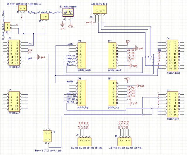
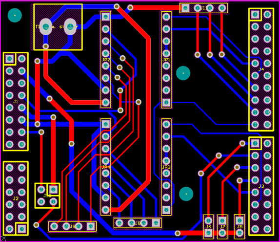
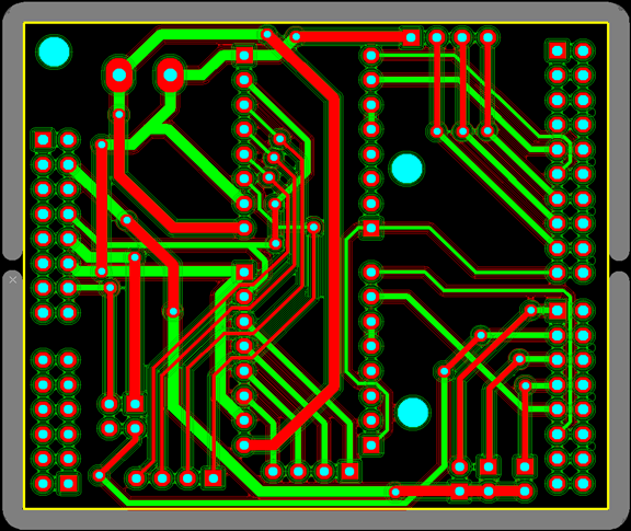
Here we decide to create our personal "UDOO Shield" that allowed us to use less jumper wires and to have stronger connection between our components. You can find our schematic and circuit routing below this section, with some comments that should help you understand everything. Note that you can use more jumper wires instead, if you can't create your personal "shield".
What we see after the shield is created is this:
The device that is designed is based on an interaction with the user quick and easy, in fact the machinery is not fully automatic. First, using a HUB, connect the mouse and keyboard to the UDOO NEO and the monitor via HDMI to Micro HDMI cable. When the board is powered up, what prompts the user to perform is a short configuration walk through the Terminal "LXTerminal" installed on the operating system and on the desktop. After that, just simply connect the USB socket barcode reader and go read the barcode on the desired test tube. Assuming that the card is powered and that the desktop is loaded, what the user needs to do is:
- Open "LXTerminal" on your desktop;
- Type the following line to reach the directory where the C code program that opens the communication between the A9 processor and the M4 processor is (you can find the C program we are talking about in the "Code" section listed below):
cd /PathOfTheProgram/
- And then, to launch the program, just type:
./NameOfTheProgram.
Once this is done, the system will attend untill the barcode is entered from the keyboard. This task is done by the barcode reader, which emulates pressing the buttons on the keyboard (whence "keyboard emulation") and deliver. The communication between the A9 and the M4 side containing the Arduino sketch that encodes the incoming number, and uses it to move the motors in the right position, is done automatically via the internal communication channel specifically implemented through the "Serial" object on the Arduino sketch and accessible from the A9 via Terminal with the code "/dev/ttyMCC". It is a "virtual" serial who uses shared memory to exchange data on the chip between the two cores of the FreescaleTM i.MX 6SoloX application processor.
Now we explain how our entire system will work. The mechanism has been designed in such a way to give time to the operating system to load before you can activate its main function. This expectation is shown to the user via the red status LED, that turns on for about 45 seconds, pointing the user to wait. After 45 seconds, the Green LED lights up, indicating that the machine is ready. Here there are two cases: if the stepper motors are already in the initial position, you will see light up for a short time the yellow LED (indicating the movement of the motors, then also warns the user from reading other codes) before returning on the Green LED. From here on, the machine is ready to read the code on the test tube; if the motors are not found in the initial position, you will see the yellow LED lights up and the engines move until they reach their "zero". Note that the "initial position" was performed with the help of two normally open push-buttons, one for the "step_small" and one for the "step_big". When they are pressed, the pulse is read from NEO and block the movement of the engines themselves. Lastly, you can see the movement of the servo motor that closes underneath the hole where will go in the test tube.
At this point, the user should read the following code on the tube with the barcode reader, which is manufactured as "code 39" containing 8 digits (or even letters wanting). Of these 8 digits, we know that the last 2 must belong to the location in the tube rack. To make it all the more automatic, the barcode reader was set in such a way as to read only the last two digits on barcode, discarding all first 6 digits and/or numbers that can be traced back to the patient and other peculiarities. In this case, we conjecture that the penultimate digit represents the movement along the Y axis (or "step_smal"), decoding the line number of the 5x10 tube rack with the numbers from 0 to 4; the last digit instead, decodes the column number with numbers from 0 to 9, which results in the movement of the "step_big" along the x-axis. At this stage it is important to point out the presence of a button named "Deck (1/2)" located on the top of the box that allows the user to choose which "Deck" should be used, just by holding it for a very short time. By default, the used deck is "Deck1", where the machine can get the tubes from 0 to 49. If pressed, the deck switch to "Deck2" and you can see the change from the yellow LED, that flashes twice; now, the machine will work correctly with the test tubes from 50 to 99. Of course, filled the tube rack relative to the "Deck2”, you can return to the "Deck1" by running the same operation and checking that the yellow LED flashes once (Note: the system does not recognize the dimensions of the tube rack, so it always use one from 5x10. It also assumes that the test tubes contain a number that ranges from 0 to 99). This operation has been implemented in code by defining a variable "Change_deck", that depending on the Deck may be 0 or 5, so before you move the motor along the Y axis (rows), the system performs the subtraction between the read number and the variable "Change_deck" (see the Arduino code in the "Code" section below). In this situation, depending on the deck and the number on the test tube, we can get four cases:
a. The button named "Deck" is not pressed and the tube contains a number from 0 to 49. In this case the system will place the tube in the right place without particular precautions;
b. The button named "Deck" is not pressed and the tube contains a number from 50 to 99. In this case the system recognizes that the current tube does not belong to the current Deck and then releases it along a ramp located near the "zero", allowing the user to recover it and indicating that the tube should be reinserted once the Deck is changed;
c. The button named "Deck" is pressed and the tube contains a number from 0 to 49. In this case the operation is similar to the case "b";
d. The button named "Deck" is pressed and the tube contains a number from 50 to 99. This case is the categorical dual of the case "a".
Once the code is read, the user has three seconds to correctly positioning the tube inside the hole on the top of the plastic frame discoverable by the arrow that says "Provetta". At this stage, the servo motor is in position to cover the below hole containing the test tube, so that it cannot fall over. After three seconds, the yellow LED will turn on and the engines will begin to move to the right position, the servo will rotate 100 degrees to allow the fall of the tube and then will rotate in the opposite direction to close the hole. Then the engines will move until the two limit switches (NO buttons) were pressed, then the yellow LED will turn off and the Green LED will turn on, indicating the machine readiness for another new tube.
This video will show you in a better way how does it works, go search it on "Youtube":
Personal UDOO shield - Schematic
Personal UDOO shield - Circuit routing


_3u05Tpwasz.png?auto=compress%2Cformat&w=40&h=40&fit=fillmax&bg=fff&dpr=2)

Comments