


After building the basic structure of my ACEBOTT smart home, I wanted to add a realistic security feature: a card‑controlled door lock. This project uses the RFID RC522 I2C module that comes with the Level 2 kit. Unlike traditional RC522 modules that require four SPI wires, this I2C version needs only two data lines – making wiring clean and simple.
When an authorized card is tapped, a servo motor unlocks the door 🤩🔓 If an unrecognised card is used, a red LED flashes and a buzzer sounds to clearly signal denied access 😧🔐🚨 All logic runs on the ACEBOTT ESP32 using the dedicated libraries provided with the kit.
This project is perfect for beginners who want to learn about RFID, I2C communication, and access control logic – all while expanding their ACEBOTT smart home.
Hardware
- ACEBOTT ESP32 Smart Home Edu Kit – Level 2
https://acebott.com/product/acebott-qe024-esp32-5-in-1-smart-home-education-kit-level-2/
- (includes main board, servo, LED module, buzzer module, RFID I2C module, and mechanical parts)
- RFID RC522 I2C Module (ACEBOTT version)
- Servo motor SG90
- LED module (red)
- Buzzer module
- Acrylic structural parts (door, base, signboard, LUMI, etc.)
Software
- ACECode (Scratch‑based) OR Arduino IDE
🔐 What is RFID technology and how does it work?An RFID (Radio Frequency Identification) system consists of two main components: a reader and a tag.
The RFID reader contains a radio frequency module and an antenna that creates a high-frequency electromagnetic field around it.
The RFID tag is attached to whatever object we want to identify or track. Most tags are passive, which means they don’t have batteries or their own power source. Instead, they wait quietly until they enter the reader’s electromagnetic field.
When a tag enters this field, the radio waves from the reader create a tiny electrical current in the tag’s antenna. This small current gives the tag just enough power to wake up its microchip. The microchip contains important information about the object the tag is attached to. Once powered up, the tag sends this information back to the reader. This process is called backscatter, where the tag doesn’t generate its own radio signal but instead modifies (or “modulates”, if you prefer the technical term) the reader’s signal.
The reader picks up this modified signal, decodes the information, and sends it to a computer or microcontroller for further use.
While most RFID tags are passive, there are also active tags that have their own power source, like a small battery. These active tags can communicate over much greater distances because they don’t need to rely on the reader’s signal for power.
RFID Frequencies
RFID systems operate at different radio frequencies, each with special advantages:
- Low Frequency (LF): These work at shorter ranges and are often used for animal tracking or access cards.
- High Frequency (HF): These offer a good balance of range and data transfer speed, making them perfect for library books, payment cards, and many hobbyist projects.
- Ultra-High Frequency (UHF): These can be read from farther away and are excellent for tracking inventory in warehouses or items moving quickly on assembly lines.
RFID RC522 I2C Module
The RC522 RFID reader that we’ll be working with operates in the High Frequency range, specifically at 13.56 MHz. This makes it ideal for projects where you need to read tags from a few inches away, like electronic door locks, attendance systems, or interactive displays.
The module typically comes with two types of RFID tags:
- A card that looks similar to a credit card
- A key fob that can attach to your keychain
The RFID RC522 IIC module is a common radio frequency identification module capable of wirelessly recognizing and reading/writing data from nearby electronic tags. It communicates with the main control board or microcontroller via the IIC interface.
SDA: The data pin of the IIC interface ,connect the SDA pin of the controller board.
SCL: The clock pin of the IIC interface ,connect the SCL pin of the controller board.
V: Connect the 5V pin of the controller board
G: Connect the GND pin of the controller board.
The IC card (key fob), or integrated circuit card, has the capability to write and store data within its chip. IC cards are divided into contact and contactless types. In this project, we are using a contactless IC card, which communicates with the reader/writer through RFID technology.
All mechanical parts are laser‑cut acrylic and fit together without screws. Follow the kit’s official Assemble documentation – Level 2 for detailed visuals.
Step 1: Installing the RFID RC522 I2C Module.
Step 2: Installing the gear.
Step 3: Installing the door.
Step 4: Installing the Servo SG90.
Step 5: Installing the LED module and the buzzer module.
Step 6: Installing RFID and the signboard on the base.
Step 7: Installing the LUMI.
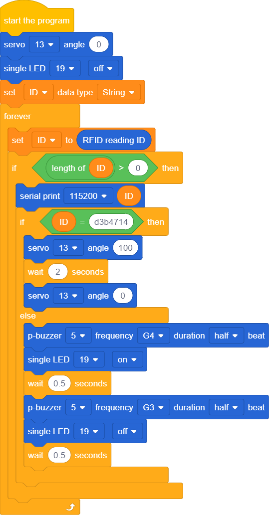
- Initialize the RFID reader, servo, LED, and buzzer.
- Wait for a card to be tapped.
- Read the card’s unique ID (UID).
- Compare it with the pre‑stored authorized UID.
- If matched: servo rotates to 100° (door opens), waits 2 seconds, then returns to 0° (door closes).
- If not matched: buzzer beeps twice at different frequencies, red LED flashes.
- Return to waiting state.
Before the code will work for your cards, you need to find their unique IDs:
- Open Serial Monitor
- Set baud rate to 115200.
- Tap your card on the RFID module.
- The Serial Monitor will display a hex string like d3b4714.
- Copy this string and paste it into the code
Watch two real‑world tests of the RFID door lock:
❌ Denied – wrong card → red LED + buzzer
✅ Granted – correct card → door opens
Built with the ACEBOTT ESP32 kit and RC522 I2C module.
With just a few lines of code and four wires, I added a secure, card‑based access system to my ACEBOTT smart home. The same principle can be extended to multiple cards, a database of UIDs, or even logging access times.
This project is a great foundation for learning RFID and I2C – and it makes your smart home model much cooler!


Comments