


Hardware components | ||||||
 |
| × | 1 | |||
First, I read the Introduction to Arduino Uno
I got stuck in the very last section when I couldn’t find the “examples” folder in the Arduino folder to copy the “SIK_Guide_Code_32” into. After Contents > Resources, I did not have a “Java” folder. Therefore, I created a “Java > examples” path and pasted the “SIK_Guide_Code_32” into the folder. However, the examples didn’t show up under Files > Examples in the Arduino software. I looked back again to try and find the Java file, and it turns out that the file path provided was incorrect. It should actually be in Contents > Java > examples > SIK_Guide_Code_32, not under Resources.
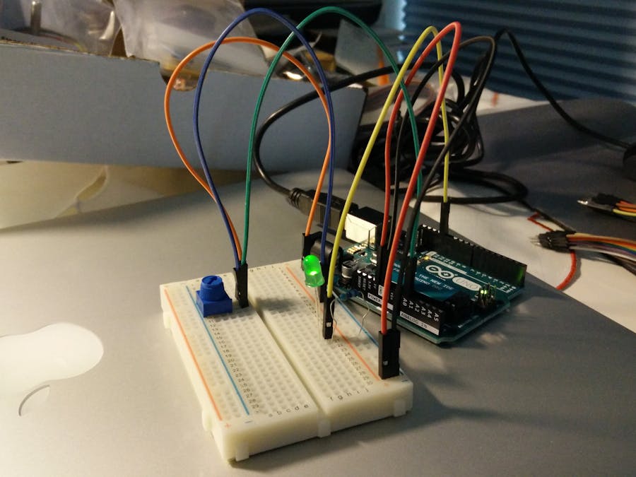
Experiment 1: Blinking and LED
I then could not find a packet labeled “jumper wires”, so I Googled what jumper wires looked like were and discovered they were the wires labeled “Premium Wire Pack – for Kits”. I also learned that the color does not matter, but it made it easier to follow the circuit diagram if I used the same colors as they did.
Experiment 2: Reading a Potentiometer
At first I wasn’t able to find the potentiometer, because I was looking for a much larger piece. However, I was finally able to locate it in the bag with the words “10k trimmer”. The potentiometer was actually about ½ an inch long and wide.
Illustrator Introduction:
Origami folding:
https://www.youtube.com/watch?v=kcr3b3UT8kU
/*
SparkFun Inventor's Kit
Example sketch 01
BLINKING A LED
Turn an LED on for one second, off for one second,
and repeat forever.
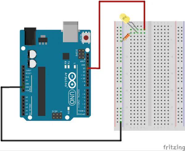
Hardware connections:
Most Arduinos already have an LED and resistor connected to
pin 13, so you may not need any additional circuitry.
But if you'd like to connect a second LED to pin 13, or use
a different pin, follow these steps:
Connect the positive side of your LED (longer leg) to Arduino
digital pin 13 (or another digital pin, don't forget to change
the code to match).
Connect the negative side of your LED (shorter leg) to a
330 Ohm resistor (orange-orange-brown). Connect the other side
of the resistor to ground.
pin 13 _____ + LED - _____ 330 Ohm _____ GND
(We always use resistors between the Arduino and and LEDs
to keep the LEDs from burning out due to too much current.)
This sketch was written by SparkFun Electronics,
with lots of help from the Arduino community.
This code is completely free for any use.
Visit http://learn.sparkfun.com/products/2 for SIK information.
Visit http://www.arduino.cc to learn about the Arduino.
Version 2.0 6/2012 MDG
*/
// Welcome to Arduino!
// If you're brand-new to this, there will be some new things to
// learn, but we'll jump right in and explain things as we go.
// The Arduino is a tiny computer that runs programs called
// "sketches". These are text files written using instructions
// the computer understances. You're reading a sketch right now.
// Sketches have computer code in them, but also (hopefully)
// "comments" that explain what the code does. Comments and code
// will have different colors in the editor so you can tell them
// apart.
// This is a comment - anything on a line after "//" is ignored
// by the computer.
/* This is also a comment - this one can be multi-line, but it
must start and end with these characters */
// A "function" is a named block of code, that performs a specific,
// well, function. Many useful functions are already built-in to
// the Arduino; others you'll name and write yourself for your
// own purposes.
// All Arduino sketches MUST have two specific functions, named
// "setup()" and "loop()". The Arduino runs these functions
// automatically when it starts up or if you press the reset
// button. You'll typically fill these function "shells" with your
// own code. Let's get started!
// The setup() function runs once when the sketch starts.
// You'll use it for things you need to do first, or only once:
void setup()
{
// The Arduino has 13 digital input/output pins. These pins
// can be configured as either inputs or outputs. We set this
// up with a built-in function called pinMode().
// The pinMode() function takes two values, which you type in
// the parenthesis after the function name. The first value is
// a pin number, the second value is the word INPUT or OUTPUT.
// Here we'll set up pin 13 (the one connected to a LED) to be
// an output. We're doing this because we need to send voltage
// "out" of the Arduino to the LED.
pinMode(13, OUTPUT);
// By the way, the Arduino offers many useful built-in functions
// like this one. You can find information on all of them at the
// Arduino website: http://arduino.cc/en/Reference
}
// After setup() finishes, the loop() function runs over and over
// again, forever (or until you turn off or reset the Arduino).
// This is usually where the bulk of your program lives:
void loop()
{
// The 13 digital pins on your Arduino are great at inputting
// and outputting on/off, or "digital" signals. These signals
// will always be either 5 Volts (which we call "HIGH"), or
// 0 Volts (which we call "LOW").
// Because we have an LED connected to pin 13, if we make that
// output HIGH, the LED will get voltage and light up. If we make
// that output LOW, the LED will have no voltage and turn off.
// digitalWrite() is the built-in function we use to make an
// output pin HIGH or LOW. It takes two values; a pin number,
// followed by the word HIGH or LOW:
digitalWrite(13, HIGH); // Turn on the LED
// delay() is a function that pauses for a given amount of time.
// It takes one value, the amount of time to wait, measured in
// milliseconds. There are 1000 milliseconds in a second, so if
// you delay(1000), it will pause for exactly one second:
delay(1000); // Wait for one second
digitalWrite(13, LOW); // Turn off the LED
// delay(1000); // Wait for one second
delay(100); // Wait for 0.1 second
// delay(2000); // Wait for two seconds
// All together, the above code turns the LED on, waits one
// second, turns it off, and waits another second.
// When the computer gets to the end of the loop() function,
// it starts loop() over again. So this program will continue
// blinking the LED on and off!
// Try changing the 1000 in the above delay() functions to
// different numbers and see how it affects the timing. Smaller
// values will make the loop run faster. (Why?)
}
/*
SparkFun Inventor's Kit
Example sketch 02
POTENTIOMETER
Measure the position of a potentiometer and use it to
control the blink rate of an LED. Turn the knob to make
it blink faster or slower!
What's a potentiometer?
A potentiometer, or "pot" for short, is a control knob.
It's the same type of control you'd use to change volume,
dim a lamp, etc. A potentiometer changes resistance as it
is turned. By using it as a "voltage divider", the Arduino
can sense the position of the knob, and use that value to
control whatever you wish (like the blink rate of an LED,
as we're doing here).
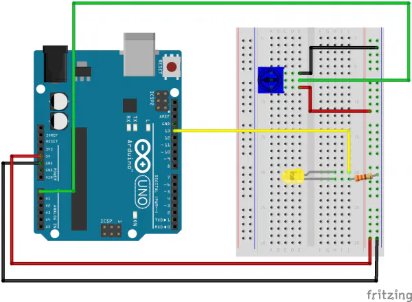
Hardware connections:
Potentiometer:
Potentiometers have three pins. When we're using it as a
voltage divider, we connect the outside pins to power and
ground. The middle pin will be the signal (a voltage which
varies from 0 Volts to 5 Volts depending on the position of
the knob).
Connect the middle pin to ANALOG IN pin 0 on the Arduino.
Connect one of the outside pins to 5V.
Connect the other outside pin to GND.
(TIP: if once your program is running, the knob feels
"backwards", you can swap the 5V and GND pins to reverse
the direction.)
LED:
Most Arduinos already have an LED and resistor connected to
pin 13, so you may not need any additional circuitry.
But if you'd like to connect a second LED to pin 13, or use
a different pin, follow these steps:
Connect the positive side of your LED (longer leg) to
Arduino digital pin 13 (or another digital pin, but don't
forget to change the code to match).
Connect the negative side of your LED (shorter leg) to a
330 Ohm resistor (orange-orange-brown).
Connect the other side of the resistor to ground.
This sketch was written by SparkFun Electronics,
with lots of help from the Arduino community.
This code is completely free for any use.
Visit http://learn.sparkfun.com/products/2 for SIK information.
Visit http://www.arduino.cc to learn about the Arduino.
Version 2.0 6/2012 MDG
*/
// Welcome back! In this sketch we'll start using "variables".
// A variable is a named number. We'll often use these to store
// numbers that change, such as measurements from the outside
// world, or to make a sketch easier to understand (sometimes a
// descriptive name makes more sense than looking at a number).
// Variables can be different "data types", which is the kind of
// number we're using (can it be negative? Have a decimal point?)
// We'll introduce more data types later, but for the moment we'll
// stick with good old "integers" (called "int" in your sketch).
// Integers are whole numbers (0, 3, 5643), can be negative, and
// for reasons we won't go into right now, can range from -32768
// to 32767. (Don't worry, if you need to work with larger numbers,
// there are other data types for that. See:
// http://arduino.cc/en/Reference/VariableDeclaration
// for a list of all the data types you can use).
// You must "declare" variables before you use them, so that the
// computer knows about them. Here we'll declare two integer
// variables, and at the same time, initialize them to specific
// values. We're doing this so that further down, we can refer to
// the pins by name rather than number.
// Note that variable names are case-sensitive! If you get an
// "(variable) was not declared in this scope" error, double-check
// that you typed the name correctly.
// Here we're creating a variable called "sensorPin" of type "int"
// and initializing it to have the value "0":
int sensorPin = 0; // The potentiometer is connected to
// analog pin 0
int ledPin = 13; // The LED is connected to digital pin 13
// One more thing. If you declare variables outside of a function,
// as we have here, they are called "global variables" and can be
// seen by all the functions. If you declare variables within a
// function, they can only be seen within that function. It's good
// practice to "limit the scope" of a variable whenever possible,
// but as we're getting started, global variables are just fine.
void setup() // this function runs once when the sketch starts up
{
// We'll be using pin 13 to light a LED, so we must configure it
// as an output.
// Because we already created a variable called ledPin, and
// set it equal to 13, we can use "ledPin" in place of "13".
// This makes the sketch easier to follow.
pinMode(ledPin, OUTPUT);
// The above line is the same as "pinMode(13, OUTPUT);"
// You might be wondering why we're not also configuring
// sensorPin as an input. The reason is that this is an
// "analog in" pin. These pins have the special ability to
// read varying voltages from sensors like the potentiometer.
// Since they're always used as inputs, there is no need to
// specifically configure them.
}
void loop() // this function runs repeatedly after setup() finishes
{
// First we'll declare another integer variable
// to store the value of the potentiometer:
int sensorValue;
// The potentiometer is set up as a voltage divider, so that
// when you turn it, the voltage on the center pin will vary
// from 0V to 5V. We've connected the center pin on the
// potentiometer to the Arduino's analog input 0.
// The Arduino can read external voltages on the analog input
// pins using a built-in function called analogRead(). This
// function takes one input value, the analog pin we're using
// (sensorPin, which we earlier set to 0). It returns an integer
// number that ranges from 0 (0 Volts) to 1023 (5 Volts).
// We're sticking this value into the sensorValue variable:
sensorValue = analogRead(sensorPin);
// Now we'll blink the LED like in the first example, but we'll
// use the sensorValue variable to change the blink speed
// (the smaller the number, the faster it will blink).
// Note that we're using the ledPin variable here as well:
digitalWrite(ledPin, HIGH); // Turn the LED on
delay(sensorValue); // Pause for sensorValue
// milliseconds
digitalWrite(ledPin, LOW); // Turn the LED off
delay(sensorValue); // Pause for sensorValue
// milliseconds
// Remember that loop() repeats forever, so we'll do all this
// again and again.
}

Comments