

Hardware components | ||||||
 |
| × | 1 | |||
 |
| × | 1 | |||
 |
| × | 2 | |||
| × | 2 | ||||
 |
| × | 1 | |||
| × | 1 | ||||
 |
| × | 1 | |||
 |
| × | 1 | |||
 |
| × | 1 | |||
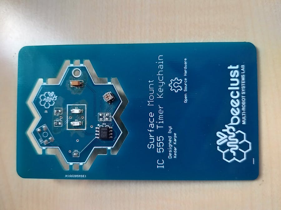
This article is about a timer-based LED keychain. The keychain has a 555 timer IC, which controls the blinking time of the two LEDs. The IC is an integrated circuit (chip) used in a variety of timer, pulse generation, and oscillator applications. The 555 can be used to provide time delays, as an oscillator, and as a flip-flop element.
The 555 timer has three modes:
- Astable Mode - It operates as an electronic oscillator. The output switches between high and low states at an adjustable frequency and pulse width.
- Monostable Mode - In this mode, the 555 functions as a "one-shot" pulse generator. This creates a delay. The external trigger causes the timer to release a single pulse at an adjustable length of time.
- Bistable Mode - The 555 can operate as a flip-flop, if the DIS pin is not connected and no capacitor is used. This mode switches between high and low states depending on two inputs.
Our 555 timer-based LED keychain will be operating in astable mode.
It's Working!In this keychain we use a 555 IC as a controller to provide timing delays for blinking of the LEDs. The 555 ICC operates in astable mode. This means there will be no stable level at the output. So the output will be swinging between high and low. There are two LEDs in this circuit. The 555 IC controls the frequency division of each LEDs.
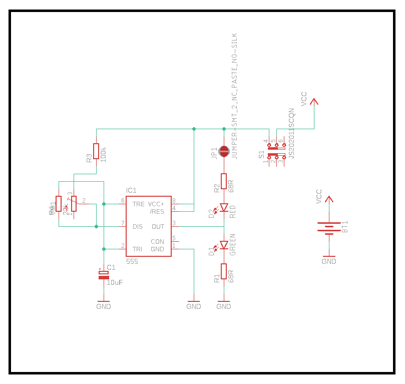
In the IC 555 pin no 2 and 6 are connected to each other. Similarly pin 4 and 8 are interconnected too. The +ve terminal of the 10 microfarad capacitor is connected to pin 2 and its -ve to the ground. The 100k resistor is connected between pin 8 and 7. The 22k resistor between pin 6 and 7. Out of the two LEDs, the -ve terminal of D1 is connected to pin 3 and its +ve to a 68R resistor which is further connected to ground. Similarly the +ve terminal of LED, D2 is connected to pin 3 and its -ve to a 68R resistor which is further connected to a trim pot. The capacitor(10 microfarad) gets charged and discharged continuously. The time taken for charging and discharging determines the flashing rate of the LEDs.
A trimpot or trimmer potentiometer is a small potentiometer which is used for adjustment, tuning and calibration in circuits. These trim pots are used here for adjusting the frequency of these LEDs in this keychain. The entire circuit is powered using a coin cell battery.
Assemble the components as mentioned in the schematic.
The following were generated using PCBWay's Gerber View ToolYou can view your Gerber file using the following link: https://www.pcbway.com/project/OnlineGerberViewer.html
AcknowledgementsI thank PCBWay for manufacturing and delivering PCBs of great quality
.PCBWay is one of the most experienced PCB manufacturers in China. They offer standard PCB prototypes, flexible PCBs, aluminum PCBs, Stencils. Additionally they offer assembly service. With prices as low as 5 USD for 10 PCBs, also you may be interested in their Gerber view function.


Comments