(This project is being managed here: Project Repository)
Background HistoryThe solar panels can be charged using Maximum Power Point Tracking(MPPT). This power tracking charges the panels that are run by the sunlight. Sometimes when we do not have the facility to provide the sunlight to the solar panels to charge them like in the season of rains and floods then we need to charge our panels. This solar panel battery charger helps us there. LT3652 is a DC to DC converter that provides the most efficient charging tracking to solar batteries. Because solar panels are very efficient and optimized in providing light to our homes from sunlight.
How LT3652 works?LT3652 is the most efficient charging regulator. It is a DC to DC converter. First, they receive the input from the solar panels in the form of DC then they convert it into the high frequency in the form of AC signals, and in the last, they convert it into the exact same voltages and current that is DC as per solar batteries requirements.
For instance, you have a very low battery e.g. 12V this LT3652 MPPT will take around 17V at 7A and will convert it as low current then the battery will get around 12V at 10A.mps at 12 volts. Leftover power would be 130W which would be sufficient.
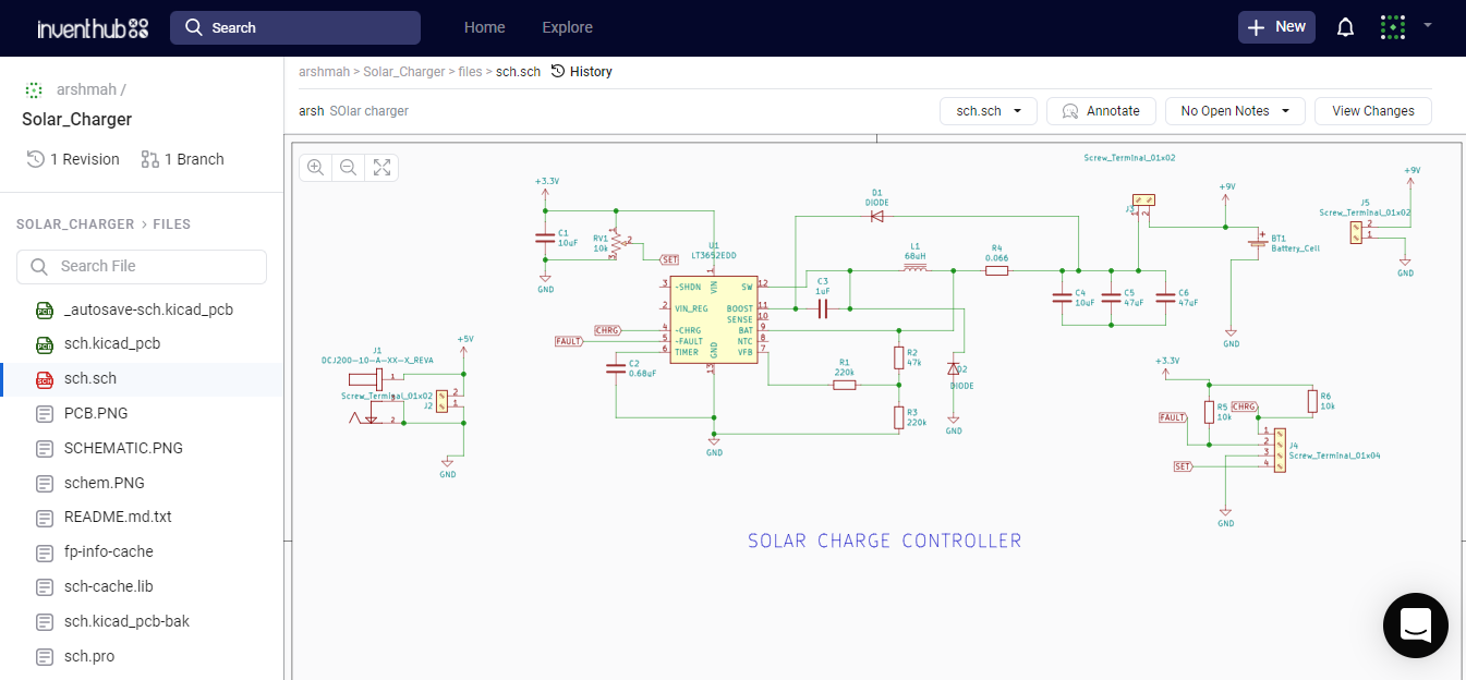
Schematic diagramIn this schematic, we can see LT3652 MPPT solar charger regulator. That is acting as a DC to DC converter to lower down, increase, and change DC to AC and again AC to DC to charge the solar panel batteries. The barrel jack is used as a switch that will disconnect the battery inside the panel and will connect the external battery and it will charge the panel battery when the solar panel is not charged.
Inventhub provides us the facility to make projects online. After completing the schematic diagram on KiCAD I have shared it online on Inventhub with our collaborators and service providers.
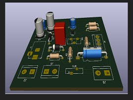
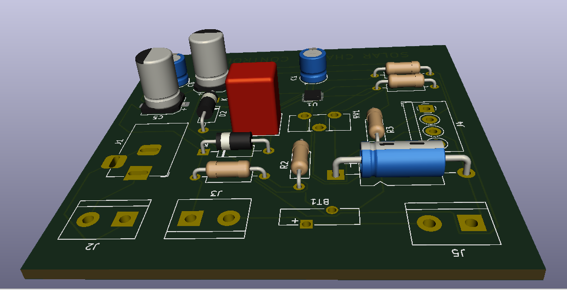
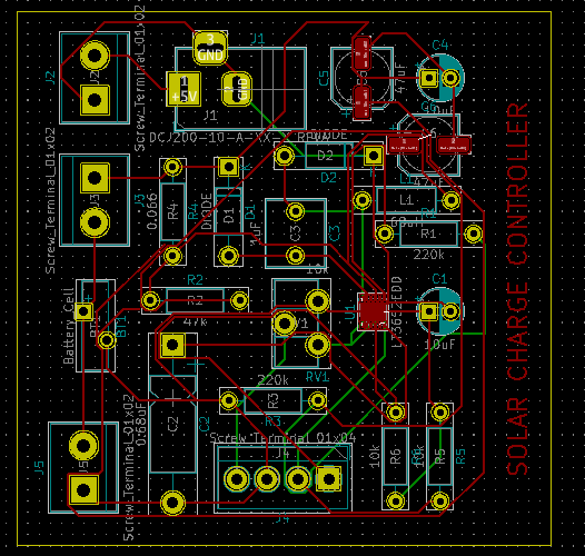
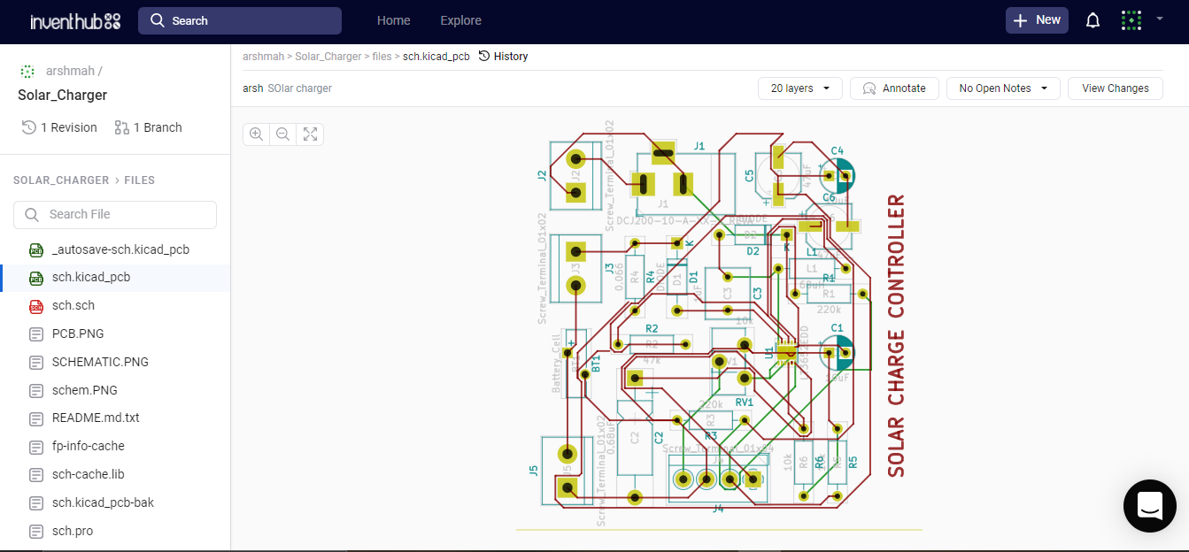
PCB designThis is the PCB design of the project. This can be done by converting the schematic file to the PCB file. We have an option to choose the size of the board as per requirements and dimensions of the components. We can also check the errors in our PCB design by going into Inspect→Design Check Rule. This will provide us the facility to find the errors in our design. The solar charge controller is to charge the solar batteries so we need to be very careful while creating its PCB design that we do not miss any connection because here we are dealing with the solar panels that are very costly and used to run the electricity of the house.
I have shared it online on Inventhub with service providers to get the designed board in the hardware.
https://inventhub.io/c/arshmah/Solar_Charger/tree/default this is the link where you can see my whole design file.
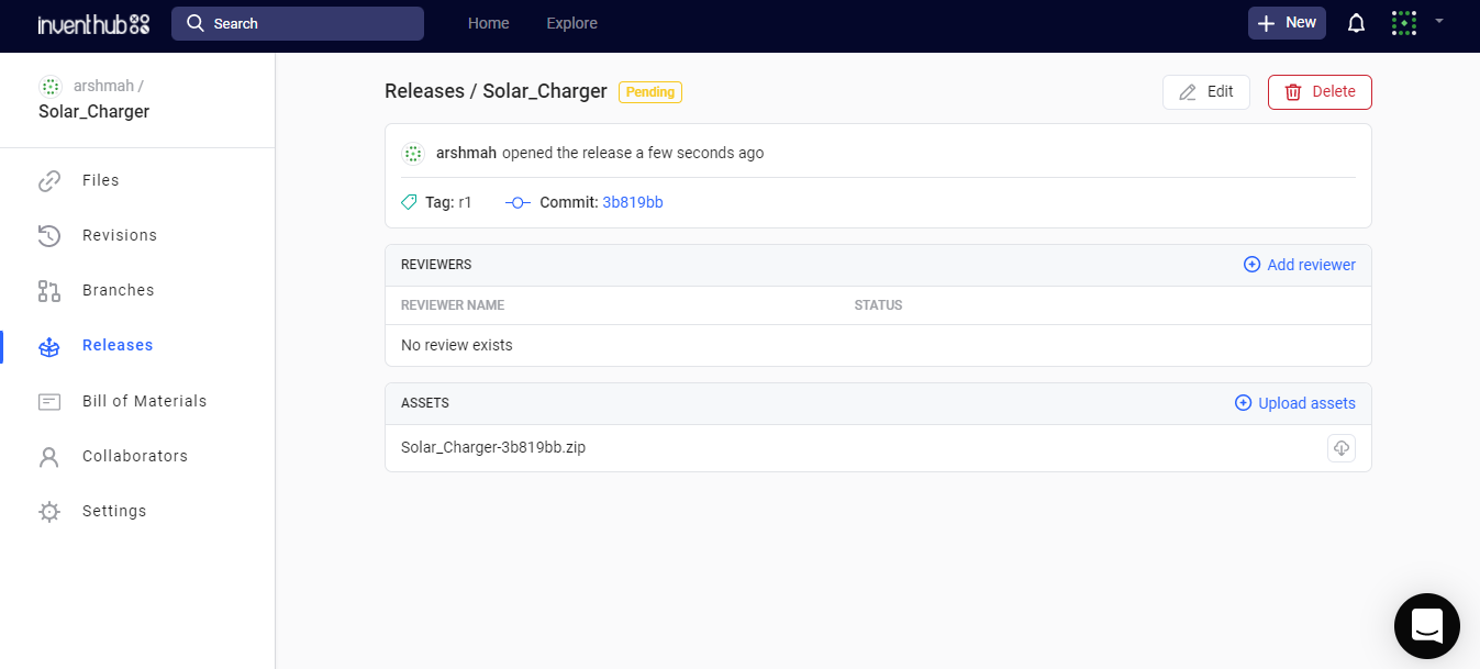
Design ManufacturingAfter finalizing the design I need to fabricate my PCB. For this, I need to communicate with the manufacturer to send him my project files for fabrication. I used the online Inventhub to create a release of my project in the form of a zip file and uploaded it. My manufacturer now can export this file and can fabricate my PCB design easily.
This link will show you the release of my project https://inventhub.io/c/arshmah/Solar_Charger/releases/pending
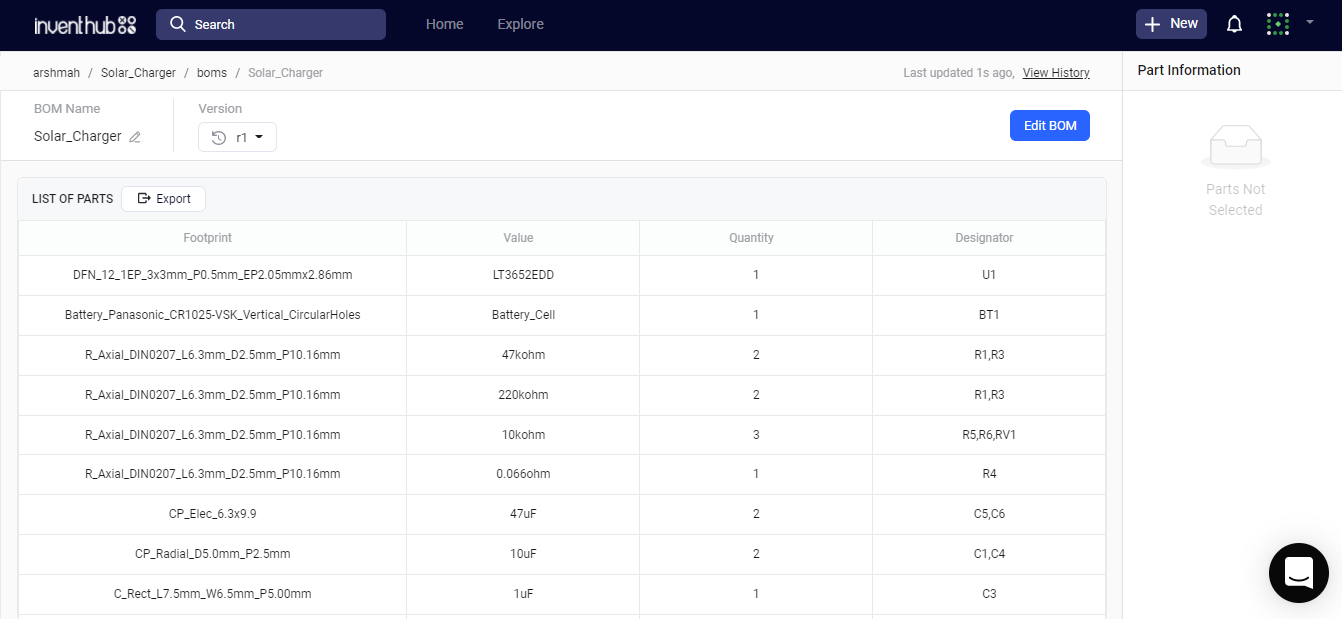
Bill of MaterialsTo solder the components on the fabricated PCB, I need to order the components which I have used in my design on KiCAD. I have created the bill of materials with all the footprints of each component along with value and quantity and uploaded that BOM on the Inventhub. Now the component provider can export this file to view each component and he can send me the components of my requirements. Here you can see the bill of material of my project https://inventhub.io/c/arshmah/Solar_Charger/bom/list


Comments