The decoder IC is an electronics circuit which is consisting of an inbuilt op
amp and to separate low and high frequencies. The tone which is generated
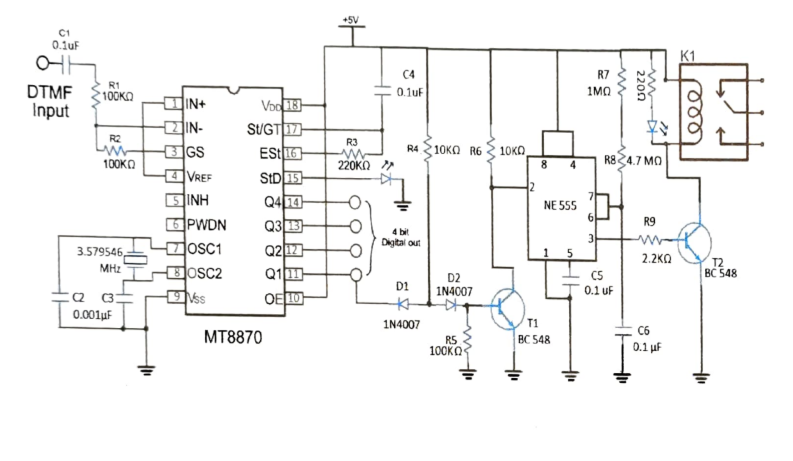
from the mobile is sent through a capacitor and the resistor of the DTMF.
Pin no 18 is Vcc and pin no 9 GND.
Pin no l is a non-inverting pin, which is connected to the pin 4.
Pin no 3 is the output of the operational amplifier, which is feedback to the
pin 2.
3 The pin no 7 and pin no 8 is connected to the crystal oscillator of both pins.
Pin no 15 is the data interconnection pin is connected on a LED.
11, 12, 13 and 14 pins are output pins that are connected DTMF pins. Then
DTMF is connected to a monostable multi vibrater
We use only pin no 11 to trigger the 555 tinmer.
A transistor (T1) is use to make trigger pulse of the monostable multi vibrater
circuit.
A transistor (T2) is use to switching purpose of5 volt relay.
A LED is parallely connected on the relay and a resistor is connected on series
to save the LED from high current.


Comments