

Description
Thumbing through instagram, I find a post by @davedarkocom showing that all the components for his good habit tracker, inspired by Simone Giertz, had arrived.
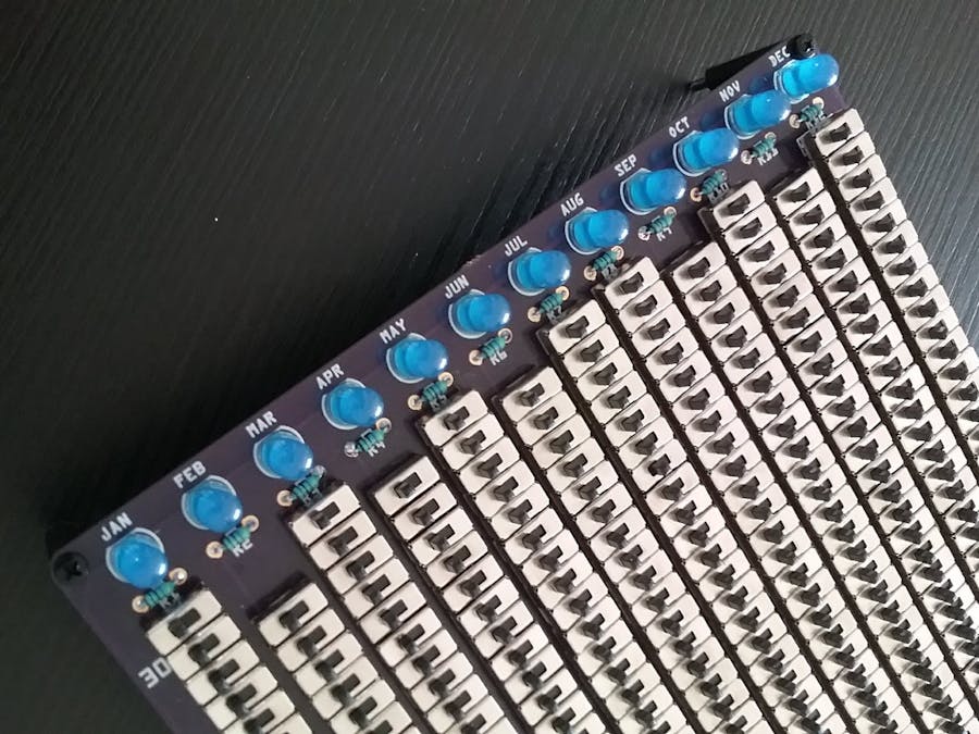
Something about the sheer absurdity of putting 30 switches in series to light up an LED and doing it 12 times clicked with me. One thing led to another and about an hour later, I had a complete Fritzing PCB (don't tell Brian Benchoff) uploaded to OshPark.
I think I err... invested... about 8 hours soldering this.
Details
As a certain Thought Leader Life Coach says: "the best way to start a good habit is by doing it every day". This device will help you with that by tracking whether a goal has been accomplished that day or not and rewarding you at the end of the month by lighting an LED if the task has been performed every day of the month.
The PCB design makes assembling your own habit tracker easier by taking care of the connections between the switches. As this device reinforces an all-or-nothing mentality, it might be beneficial to work out some forgiveness arrangement in order to make it possible to make up missed days.
The schematic for this is simple. A power plug leads to a master on/off switch. The output of the master switch feeds the first switch in each month column. Each switch in a column is wired in series to the next. The last switch leads to a 1/8W resistor and an LED. The other leg of all the LEDS are tied together and return down the left side of the board to the power plug.
The switches were selected because that's what I was using for the Sinclair Scientific Calculator project and was familiar with them. The center pin is the common. If the stem is thrown to the left, the center and left pins are bridged. If the stem is thrown to the right, the center and right pins are bridged.
You can feed the switches from the left pin and get the output from the center or feed them from the center and get the output from the left pin.
The polarity of the power plug is not marked. The supply voltage is not marked. The size of the resistor is not marked. The LED polarity is a suggestion. All of those details are left to the user. If in doubt, solder the master switch and a switch column first and then work out the details. I ended up selecting a 9V plug, 4.7K resistor and a blue led, because those are the things I had on hand.
The next step is to design a laser cut base and alignment jig to grab all the switch stems.
Smaller Simone Giertz's Good Habit Tracker by @arduinoenigma is licensed under a Creative Commons Attribution-ShareAlike 4.0 International License.
Based on a work at https://www.instagram.com/p/BdZFs3MAqHR/.
Switch Alignment Jig by SamPerry is licensed under a Creative Commons Attribution 4.0 International License.
I saw DaveDarkoCom instagram post first
The original insanity, Simone's Tracker
Get the Gerber Files for the calendar at OSHPark
@arduinoenigma instagram pictures for this project
Order a motivational board at PCBWay
This project got featured on Hackaday's homepage
Build instructions
Step 1
The Habit Tracker PCB can be ordered from @oshpark or PCBWay (@Anson)
https://oshpark.com/shared_projects/VAJZCRZ8
https://www.pcbway.com/project/shareproject/W102531ASU6_MotivationalBoardV1Prod.html
Step 2
This jig by will help you install the switches in alignment.
https://www.thingiverse.com/thing:3018815
Step 3
This circuit is very forgiving. It's only an LED, and current limiting resistor in series with an inordinate amount of switches. The LEDs for different months do not have to be the same color. Experiment in a protoboard with the desired or available LED and current limiting resistors to ensure they will work. If no protoboard is available, solder the switches for a whole month first and then hold the resistor and the LED by hand.
I ended up using 9V, 4.7K and Blue LEDs because I had that on hand.
Step 4
Insert all the switches in a month and use the 3D printed alignment jig to hold them in place. Flip the board and solder them
Step 5
If you have not decided on a current limiting resistor and LED color, this is the time. Solder the master power switch (below and to the left of the January column). Solder the power leads for the voltage source available and experiment with resistor sizes and LEDs.
Do not solder the LED at this time, wait until all columns have been soldered.
Repeat steps 4 and 5 until all 12 months have switches and current limiting resistors soldered.
Step 6
Power the circuit and flip all the switches in a month to the left (on position). Flip the master power switch to the left also. Insert an LED at the end of the column and verify it light up. If it does not, flip it. If it still does not illuminate, check your work. Verify the batteries are not dead, measure power to each switch leg going up the month column.
Once the LED has been tested to work, solder it.
Repeat for all 12 months.
Step 7
The PCB has 2.5mm standoff holes in the corner. Insert some standoffs there.
Step 8
Decide on a habit to track and flip a switch to the left for each day the goal selected is met. If starting at the middle of the month, flip all the switches before today to the left.
Decide on a protocol for making up missed days. This will ensure the board is useful even if a day or two are missed.
Files
Comments