// ****************************************************************************
// * *
// * Simple nice 3 color, 4 level LIGHT ORGAN with Arduino Pro Mini *
// * ver 1.0 *
// * *
// ****************************************************************************
//
//
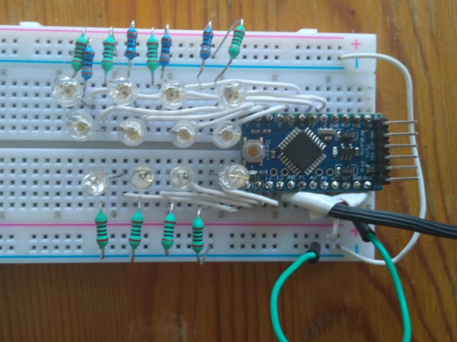
// Vcc = 3.3V
// ^
// |
// ___|___|___|___|___|___|___
// | GND GND VCC RXI TXD DTR | GND
// |TXD RAW|
// | |
// |RXI GND||
// | |
// |RST RST|
// | |
// |GND VCC|
// R1=300R___ red LED1 | | < GND from integrated amplifier's phones output
// ||___|<||2 A3|
// R2=300R___ red LED2 | | < signal from integrated amplifier's phones output
// ||___|<||3 Arduino Pro Mini A2| (since no AGC the volume needs to be adjusted to get appropriate signal level so that the LEDs turn on)
// R3=300R___ red LED3 | |
// ||___|<||4 w/ ATMega328 A1|> used only for development (signal to oscilloscope to measure sampling freq.)
// R4=300R___ red LED4 | |
// ||___|<||5 8MHz/ 3.3V A0|
// R5=300R___green LED5 | | blue LED9 ___ R9= 300R
// ||___|<||6 13||>|___||
// R6=300R___green LED6 | | blue LED10 ___ R10=300R
// ||___|<||7 12||>|___||
// R7=300R___green LED7 | | blue LED11 ___ R11=300R
// ||___|<||8 11||>|___||
// R8=300R___green LED8 | | blue LED12 ___ R12=300R
// ||___|<||9 10||>|___||
// |___________________________|
//
//
#ifndef cbi
#define cbi(sfr, bit) (_SFR_BYTE(sfr) &= ~_BV(bit))
#endif
#ifndef sbi
#define sbi(sfr, bit) (_SFR_BYTE(sfr) |= _BV(bit))
#endif
#define bit_is_set(sfr, bit) (_SFR_BYTE(sfr) & _BV(bit))
//Constants and Global Variables
const int stL1 = 20; // threshold for step1 lowpass out
const int stL2 = 25; // threshold for step2 lowpass out
const int stL3 = 30; // threshold for step3 lowpass out
const int stL4 = 40; // threshold for step4 lowpass out
const int stM1 = 16; // threshold for step1 bandpass out
const int stM2 = 25; // threshold for step2 bandpass out
const int stM3 = 32; // threshold for step3 bandpass out
const int stM4 = 48; // threshold for step4 bandpass out
const int st1 = 40; // threshold for step1 highpass out
const int st2 = 55; // threshold for step2 highpass out
const int st3 = 70; // threshold for step3 highpass out
const int st4 = 80; // threshold for step4 highpass out
int samplVal = 0; //initialization of sensor variable, equivalent to EMA Y
int EMA_SVL = 0; //initialization of EMA_S very low pass
int EMA_SL = 0; //initialization of EMA_S low pass
int EMA_SM = 0; //initialization of EMA_S middle pass
int EMA_SH = 0; //initialization of EMA_S high pass
int lowpass = 0;
int bandpass = 0;
int highpass = 0;
void setup() {
// Turn off PWM timers
cbi(TCCR1A, COM1A1);
cbi(TCCR1A, COM1B1);
cbi(TCCR0A, COM0A1);
cbi(TCCR0A, COM0B1);
cbi(TCCR2A, COM2A1);
cbi(TCCR2A, COM2B1);
// Set the output pins
pinMode(13, OUTPUT); // Channel_1 low pass level 1
pinMode(12, OUTPUT); // Channel_1 low pass level 2
pinMode(11, OUTPUT); // Channel_1 low pass level 3
pinMode(10, OUTPUT); // Channel_1 low pass level 4
pinMode(A1, OUTPUT); // cycle output signal to measure sampling rate neccessary for calculating EMA alphas
pinMode(2, OUTPUT); // Channel_2 high pass level 1
pinMode(3, OUTPUT); // Channel_2 high pass level 2
pinMode(4, OUTPUT); // Channel_2 high pass level 3
pinMode(5, OUTPUT); // Channel_2 high pass level 4
pinMode(6, OUTPUT); // Channel_3 band pass level 1
pinMode(7, OUTPUT); // Channel_3 band pass level 2
pinMode(8, OUTPUT); // Channel_3 band pass level 3
pinMode(9, OUTPUT); // Channel_3 band pass level 4
// ADC initialization: https://arduino.stackexchange.com/questions/699/how-do-i-know-the-sampling-frequency
// https://www.instructables.com/id/Girino-Fast-Arduino-Oscilloscope/
// Set the sample timer's prescaler to 2, enabling max sample freq = 8000KHz/13/2 (13 is the nr of ADC succ.appr. cycles)
// actual sample frequency depends on the code (time of operations between sampling - no interrupts applied) in this case it is 20kHz
// audiophiles should not worry about missing high frequency part, because above 7kHZ there is negligible power - no influence on the lights
// ADCSRA |= B00000111;
cbi(ADCSRA, ADPS2);
cbi(ADCSRA, ADPS1);
sbi(ADCSRA, ADPS0);
EMA_SL = 0; //set EMA_S. for t=1
EMA_SVL = 0;
EMA_SH = 0;
}
void loop() {
samplVal = analogRead_za(); // read the analog input pin A0
// Simple digital filters applied with exponential moving average (EMA) algorythm:
// https://dsp.stackexchange.com/questions/40462/exponential-moving-average-cut-off-frequency
// f3db filter frequencies (and the connected EMA alpha coefficients) are selected so that EMA algorythm can be calculated with
// simple fixed operations (add, sub, bit shift: division by 2,4,8,16,32) to keep speed, float operations avoided
EMA_SVL = (samplVal / 32) + EMA_SVL - (EMA_SVL / 32); // EMA alpha very low = 1/32 -> f3db = 102 Hz @ Fs=20kHz
EMA_SL = (samplVal / 16) + EMA_SL - (EMA_SL / 16); // EMA alpha low = 1/16 -> f3db = 315 Hz @ Fs=20kHz
EMA_SM = (samplVal / 8) + (samplVal / 32) + EMA_SM - (EMA_SM / 8)- (EMA_SM / 32); // EMA alpha middle = 5/32 -> f3db = 540 Hz @ Fs=20kHz
EMA_SH = (samplVal / 2) + (samplVal / 8)+ EMA_SH - (EMA_SH / 2) - (EMA_SH / 8); // EMA alpha high = 5/8 -> f3db = 3400 Hz @ Fs=20kHz
lowpass = EMA_SL - EMA_SVL;
bandpass = EMA_SM - EMA_SL;
highpass = EMA_SH - EMA_SM;
// PORTB &= B11000000; // turn off all LEDs
// PORTD &= B00000011;
digitalWriteB_za (abs(lowpass)); // turn on Channel_1 LEDs according to lowpass value calculated with the latest sample value
digitalWriteBD_za (abs(bandpass)); // turn on Channel_3 LEDs according to bandbass value calculated with the latest sample value
digitalWriteD_za (abs(highpass)); // turn on Channel_2 LEDs according to highpass value calculated with the latest sample value
}
// analogRead function
// the code in he following link has been modified according to this application's requiremets
// https://garretlab.web.fc2.com/en/arduino/inside/hardware/arduino/avr/cores/arduino/wiring_analog.c/analogRead.html
int analogRead_za()
{
uint8_t sample_val; // sampled analog value
uint8_t tempPC; // temporary value of PORT C
// set the analog reference (high two bits of ADMUX: REFS1 = 0, REFS0 = 1 -> ADC Vref = 3.3V)
// select channel (low 4 bits of ADMUX: 00), sets A0 as analog input pin
// set ADLAR (right-adjust result) to 1
ADMUX = 0x60;
// set ready for the AD conversion
sbi(ADCSRA, ADSC);
// ADSC is cleared when the AD conversion finishes
while (bit_is_set(ADCSRA, ADSC));
// we have to read only ADCH , due to limited accuracy the 2 bits in ADCL are not needed
sample_val = ADCH;
tempPC = PORTC ^ B00000010; // Invert cycle output signal
PORTC = tempPC; // Set A1 output which enables to measure sampling rate neccessary for calculating EMA alphas
return sample_val;
}
// 3 digital write functions per 3 color channels
// https://www.arduino.cc/en/Reference/PortManipulation
void digitalWriteB_za (int val)
{
uint8_t oldSREG = SREG;
uint8_t tempPB; // temporary value of PORTB
cli();
if (val < stL1) {
PORTB &= B11000011; // all Channel_1 LEDs off
} else {
tempPB = PORTB & B11000011;
if (val < stL2) {
PORTB = tempPB | B00100000; // set pin13 = PB5 to HIGH
} else {
if (val < stL3) {
PORTB = tempPB | B00110000; // set pin13 = PB5, pin12 = PB4 to HIGH
} else {
if (val < stL4) {
PORTB = tempPB | B00111000; // set pin13 = PB5, pin12 = BB4, pin11 = PB3 to HIGH
} else {
PORTB = tempPB | B00111100; // all Channel_1 LEDs on
}
}
}
}
}
void digitalWriteD_za (int val)
{
uint8_t oldSREG = SREG;
uint8_t tempPD; // temporary value of PORTD
cli();
if (val < st1) {
PORTD &= B11000011; // all Channel_2 LEDs off
} else {
tempPD = PORTD & B11000011;
if (val < st2) {
PORTD = tempPD | B00000100; // set pin2 = PD2 to HIGH
} else {
if (val < st3) {
PORTD = tempPD | B00001100; // set pin2 = PD2, pin3 = PD3 to HIGH
} else {
if (val < st4) {
PORTD = tempPD | B00011100; // set pin2 = PD2, pin3 = PD3, pin4 = PD4 to HIGH
} else {
PORTD = tempPD | B00111100; // all Channel_2 LEDs on
}
}
}
}
SREG = oldSREG;
}
void digitalWriteBD_za (int val)
{
uint8_t oldSREG = SREG;
uint8_t tempPD; // temporary value of PORTD
uint8_t tempPB; // temporary value of PORTB
cli();
if (val < stM1) {
PORTD &= B00111111; // all Channel_3 LEDS off
PORTB &= B11111100;
} else {
tempPD = PORTD & B00111111;
tempPB = PORTB & B11111100;
if (val < stM2) {
PORTD = tempPD | B01000000; // set pin6 = PD6 to HIGH
PORTB = tempPB;
} else {
if (val < stM3) {
PORTD = tempPD | B11000000;
PORTB = tempPB;
} else {
if (val < stM4) {
PORTD = tempPD | B11000000;
PORTB = tempPB | B00000001;
} else {
PORTD = tempPD | B11000000;
PORTB = tempPB | B00000011; // all Channel_3 LEDs on
}
}
}
}
SREG = oldSREG;
}


_3u05Tpwasz.png?auto=compress%2Cformat&w=40&h=40&fit=fillmax&bg=fff&dpr=2)
Comments