

Hardware components | ||||||
| × | 1 | ||||
| × | 1 | ||||
Software apps and online services | ||||||
 |
| |||||
Hand tools and fabrication machines | ||||||
 |
| |||||
 |
| |||||
Dear makers!
I had the possibility to buy some nice RAK811 WisNode lora modules and that moment I thought I'll find lot of examples to use but what I got is some workarounds and no one is using this shield as shield.
I did a little investigation about how I can use this shield as shield and without adding any extra component like level shifter (see below). At the end I successfully made a project that is working as I promised.
My Expectations- No additional hardware component
- Debugging and AT commands at the same place for the easy development
- Switch easily between Lora setup and Arduino sketching
This shield is having the feature to setup with AT commands and more of that, the shield is preconfigured for OTAA and you basically just need to power up and it will join to your gateway. Nice.
The most easiest way to do that is:
- Set the jumpers CRx -> DRx, CTx -> DTx
- Start the Arduino IDE and open any (or empty) project
- Connect the WisNode shield to the USB port
- Open the Arduino IDE terminal on the port that is appearing and set the baudrate to 115200
- Push the shield's reset button
Nice and easy, you not need to install terminal applications and do various setup magic.
If you want to do additional setup just type in the Arduino IDE terminal (upper textfield with the Send button) at+help and you will have anything you need.
Operating voltageThe WisNodeshield is working with 3.3 volt. So pay attention here, the shield is for Arduino Uno and that is working with 5 volt. That means your Tx/Rx will not work because of the different voltage levels, so here comes the first oops!.
I understand RakWireless came out with an additional attachable level shifter but for me this is not a solution. This situation drives me to find an Arduino compatible board that is working with 3.3 volt, so the Wemos D1 R1 board was a good choice.
It is not documented by RakWireless, even I did not found any official scheme that is telling me about the additional Rx(D10)/Tx(D11) and RST(D8) pins that I discovered on my board.
The official arduino Rx/Tx is also used (D0, D1 pins). So here comes the second oops because that means the D0 pin is in short with D10 and D1 with D11, and also the D8 is used as reset and is in short with the original RESET pin.
This setup in this fashion with the Wemos board created a lot of communication problems so I basically cannot uploaded any sketch when the WisNode shell are joined with the board. The esptool simply failed to communicate with the ESP8266 chip. Playing around these pins I also discovered the WisNode cannot join to the network so I had that bad feeling about the RESET behaviour of the shield.
As a solution I decided to eliminate the additional Rx/Tx and RESET pins from the board.
Please observe there are four pins cut out from the board (the original RESET, the D8, D10 and D11 pins). At the picture you can see also a soldering stuff that is not necessary and I'll explain later.
At this moment you are ready to use the Wemos board with the Lora shield, just:
- Put the shield on the board
- Set the jumpers DRx -> Rx, DTx -> Tx
- Power on the Wemos board
- Upload the sketch below
void setup() {
  Serial.begin(115200);

  // waiting to WisNode to join to the network
  delay(20000);
}


void loop() {
  sendData(1,"1234");
  delay(10000);
}

void sendData(int port, String data){
  String command = "at+send=lora:" + (String)port + ":" + data;
  sendCommand(command);
}

void sendCommand(String atComm){
  Serial.println(atComm);
  readLora();
}

String readLora() {
  String response = "";
  while(Serial.available()){
    char ch = Serial.read();
    response += ch;
  }
  return response;
}
You can observe the Serial object is communicating directly to your lora shield with AT commands. This is a very simple approach it is easy and fast but there is no possibility to debug.
A step forwardDebugging is very important for me so I decided to do a step forward and add the feature of debugging.
What I decided to do is:
- Use the arduino SoftwareSerial feature
- Select the right pins for SoftwareSerial
- Modding if necessary
The first idea was to use the pins D10 and D11 as software serial Rx/Tx but is is failed because doing anything with those pins fails the esptool communication when I'm uploading the sketch, so I selected the pins D6 and D7.
Because the shield uses jumpers to set the communication pins and this newcomers are some custom pins I decided to solder directly the DRx-> D6 and the DTx-> D7. This also means when I'm using the shield for communication I didn't need to put the jumpers (at now those are for only when you program the shield with AT commands)
The last thing is to adopt the sketch for SoftwareSerial and the project is done.
#include <SoftwareSerial.h>

SoftwareSerial lora(D6, D7); // RX, TX

void setup() {
  Serial.begin(115200);
  lora.begin(115200);
  // waiting to WisNode to join to the network
  delay(20000);
}

void loop() {
  sendData(1,"1234");
  delay(10000);
}

void sendData(int port, String data){
  String command = "at+send=lora:" + (String)port + ":" + data;
  sendCommand(command);
}

void sendCommand(String atComm){
  Serial.println(atComm);
  lora.println(atComm);
  readLora();
}

String readLora() {
  String response = "";
  while(lora.available()){
  char ch = lora.read();
  response += ch;
  }
  Serial.println(response);
  return response;
}
As you see the Serial now is came back for debugging and the SoftwareSerial object named lora is for the AT commands.
For a fresh and updated example please visit my GitHub repo: https://github.com/aattila/LoRa/blob/master/Rak811_WisNode/Rak811_WisNode.ino
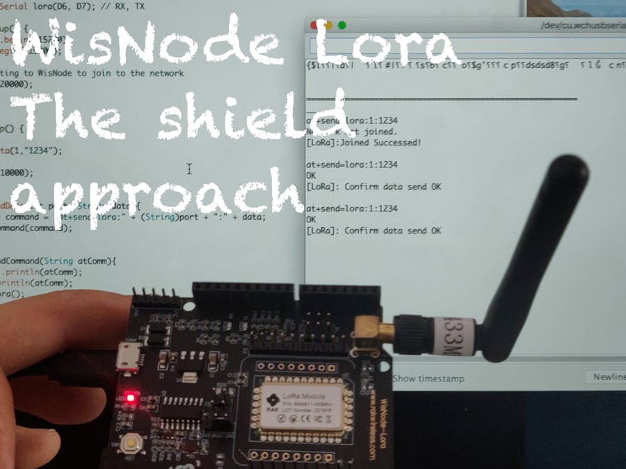
At the end you can see:
- The Wemos board is connected by USB to the laptop
- No jumpers set (but there are the soldering)
- The terminal works for debugging (you cannot AT command from there, only if you are implementing it)
- The voltage levels are right: Wemos D1 R1 is on 3.3 volt
- I cut out the pins: RESET, D8, D10, D11
- Soldered two wires: D6 -> DRx, D7 -> DTx
- Arduino IDE terminal is very OK
- SoftwareSerial for AT commands
- Serial is for debug
- No jumpers used


_M6kErcYJ84.png?auto=compress%2Cformat&w=40&h=40&fit=fillmax&bg=fff&dpr=2)


Comments