We were taught about the counter circuits and their applications in our Digital Electronics class. Up and Down counters are used widely in a variety of high frequency applications such as Traffic control systems, Digital Stopwatches, Medicinal parts counter, etc. Though, it was quite fun to design a 2 bit and 4 bit Synchronous counter on a Breadboard while using the De-bouncer as a Clock, I felt something wasn't right.. The memory elements like D-FF( Delay Flip-flops), Clock-signals, etc. made the circuit too complicated to understand for a beginner. Therefore, I decided to implement a slightly upgraded version of a synchronous counter using an Arduino. The biggest advantage is that, Arduino takes care of the Vcc(Activating voltage), GND(Ground) and the Clock signal by itself and hence, the overall circuit becomes much more simpler.
Procedure to make the circuit:
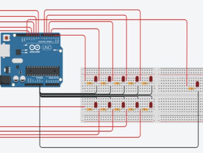
- Take a Breadboard and connect 10 LEDs, 5 on the upper side and 5 on the lower side of the middle rail. The upper 5 LEDs represent the 5 bit outputs of the Up counter while, the lower 5 represent the bits of the Down counter.
- Take 330 ohm resistors and connect them to the positive leg of the LEDs. These will be acting as the current limiting resistors in our circuit.
- Connect the negative leg of the LEDs to the GND terminal of the Arduino board beside the Analog input section.
- Connect the end of each resistor to any digital output pin and make sure that each pin is connected to a distinct resistor else, the output will not be the one we would expect.
- Now take a 2nd Breadboard and make the connections for a single LED in the exact same manner as of the first board. This LED will be working as a Clock and trigger the change of the state after each blink.
- Now, take a look at the code in given with this project. Keep this template in mind and write your own code with modifications and keep a check on all the digital pins you have used.
- After the coding part is done, run the code from your computer or online simulator to see the circuit work.
The above image describes the circuit which represents a 5 bit Synchronous Up-Down Counter (Dual counter). The top 5 red LEDs on the first breadboard represent an Up counter while, the 5 LEDs on the lower side represent a Down counter. As we have 5 bits, the Up counter will count from 0 to 2^(5)-1 (in Binary format) according to the Clock signal which has been imitated using an LED on the 2nd Breadboard. Similarly, the Down counter will count from 2^(5)-1 to 0 (in Binary format) in a synchronous manner with respect to the Clock. Both circuits count synchronously and reset after the required count stage has been achieved. Now, lets see a simulation of the circuit.
It is evident that the MSB and LSB is dynamic and keeps changing every time a new bit position is introduced. The binary number represented at every state of the system is kept on hold until a clock pulse is detected (blinking of the LED on 2nd breadboard) and as soon as, the clock pulse is detected the system changes its state to a new state. The time-delay between 2 pulses is 1 sec as per the given circuit.

_ztBMuBhMHo.jpg?auto=compress%2Cformat&w=48&h=48&fit=fill&bg=ffffff)


Comments