


Hardware components | ||||||
| × | 4 | ||||
| × | 1 | ||||
| × | 1 | ||||
_ztBMuBhMHo.jpg?auto=compress%2Cformat&w=48&h=48&fit=fill&bg=ffffff) |
| × | 1 | |||
Software apps and online services | ||||||
 |
| |||||
| ||||||
 |
| |||||
Hand tools and fabrication machines | ||||||
 |
| |||||
 |
| |||||
I made this project for those who don't want to, for some reasons, buy a robotic arm from the store. The reason I started this project is that I tried buying a robotic arm, but it couldn't even lift itself, because of its design (also it had some small servos - sg90s). So in this project, I will try to explain how to design properly a simple functional robotic arm.
In this project you will:
- calculate the mechanical advantage of the main 2 axis;
- design the robotic arm using a CAD program (SketchUp);
- 3d print the model;
- learn 3 ways of how to control the robot.
You will need:
- 50 M3 bolts and 50 M3 nuts;
- wires;
- a breadboard.
You will learn how to control the robot via:
- computer, through a USB port (recommended if you want to take note about what positions can the servos get);
- potentiometers;
- HC-05 bluetooth module.
First, you need to understand that a robotic arm is a class 1 lever, which means the fulcrum lies between the effort and the load. Down below we have the 2 principal axis of the robotic arm, which allows to move forward-back and up-down.
If you want to see how exactly the 2 axis work, you can make this parts from cardboard and fix them with a needle or something else, like I did in the photo bellow:
Next, I chose to use the MG955 motor servo, because it is small and strong (at 6V it can go up to 10 kgf·cm).
Now you must decide how long the lever will be. The longer it is, the more force the servo will put on and the weight it can carry will decrease. Its formula is effort arm * effort = load arm * load.
For example, if we use the servo2 MG995 as in the scheme bellow, the load can go up to 2 kg.
As for the servo1, the load can go up to 500g.
As we can see, because of the mechanical advantage, servo2 will play an important role in the lifting of the load. In the model attached in the hardware section, servo2 could lift a maximum load of 1.6 kg and servo1 could lift an additional 833 grams. This numbers may vary, because the servo can operate at 10 kg*cm at 6V. Take in mind that we use small batteries, that deplete quickly.
Second, you need to think about the load itself, who will be robotic claw gripper, a MG995 servo motor, and the object you want to carry. If the load is too heavy, the robotic arm will never work. Also try not to overdo it with the dimensions. The model might work but it would look weird.
The last ax will be the base servo who allows the robotic arm to turn around.
2. The CAD model:Now you can draw the robotic arm and then 3D print it. I used SketchUp to design, because it is quite simple to use it. Consider when setting the dimensions in which you will work (mm). In the hardware section(CAD) there are 2 example models: one with 2 axis, and another with 3 axis.
When you design your model, the parts of the robot must be rigid to withstand the load. If they are too thin, they risk breaking. 2.6 mm should do fine. For the components to which the engines are fixed, I doubled the thickness to not to risk curving. For the load arm, because is too long, I took a thickness of 8 mm.
When designing, I recommend that place your components (red) parallel/ perpendicular with the ground, as shown in the picture. In this way, it is more easier to design.
Also, make sure that the green parts are placed symmetrically, as shown in the picture bellow. By placing a cylinder that passes through the holes of the 2 components, it can be verified that they are placed correctly.
If you want more efficiency for the robotic arm, then the 2 axis servos should be symmetrical too. As you will see later, it will be easy to control the robotic arm with both of the servos running simultaneously.
Take in mind that the some of the parts must move freely. That means that you do not have to tighten the screws so tightly, as the components might not move due to friction. In the model bellow, I marked with blue the holes connecting those components.
You also must make sure that you make a base in a way that the robot does not fall due to the load weight. You can: 1. make a base support that is wide; 2. you attach it to a support (it may be just another robot), with bolts or glue; 3. any other idea.
Before printing the model, you can test the CAD design by simply selecting the parts and rotate them, with the center on the center of the servos.
3. 3D printing the model:!!!Take note that in this sketch I didn't make holes for the robotic arm gripper, because the dimensions may vary. It's up to you to change the sketch or just make 2 holes in the 3d printed model.
I 3d printed the 2 axis sketch, which doesn't have a base, because I will use it for a mini robot car, who can itself turn. If you don't have a 3D printer, you can use a local one, the hardware stores usually have a 3D printer, and the prices are alright (for my parts I paid 20€). You might take in note that the printed robotic arm won't be perfect. That is because the printer has an error of 0, 1 mm or even more. In my sketch, I used bolts to connect the parts. Some of them (the parts that make up the 2 axis), need a bigger hole to allow them to move. You can resolve that with an electric screwdriver. Or you can use the bolts who have a grip lenght and a thread lenght. If some of the printed parts do not match, or the motors do not fit into their holes, you can smooth with a abrasive paper.
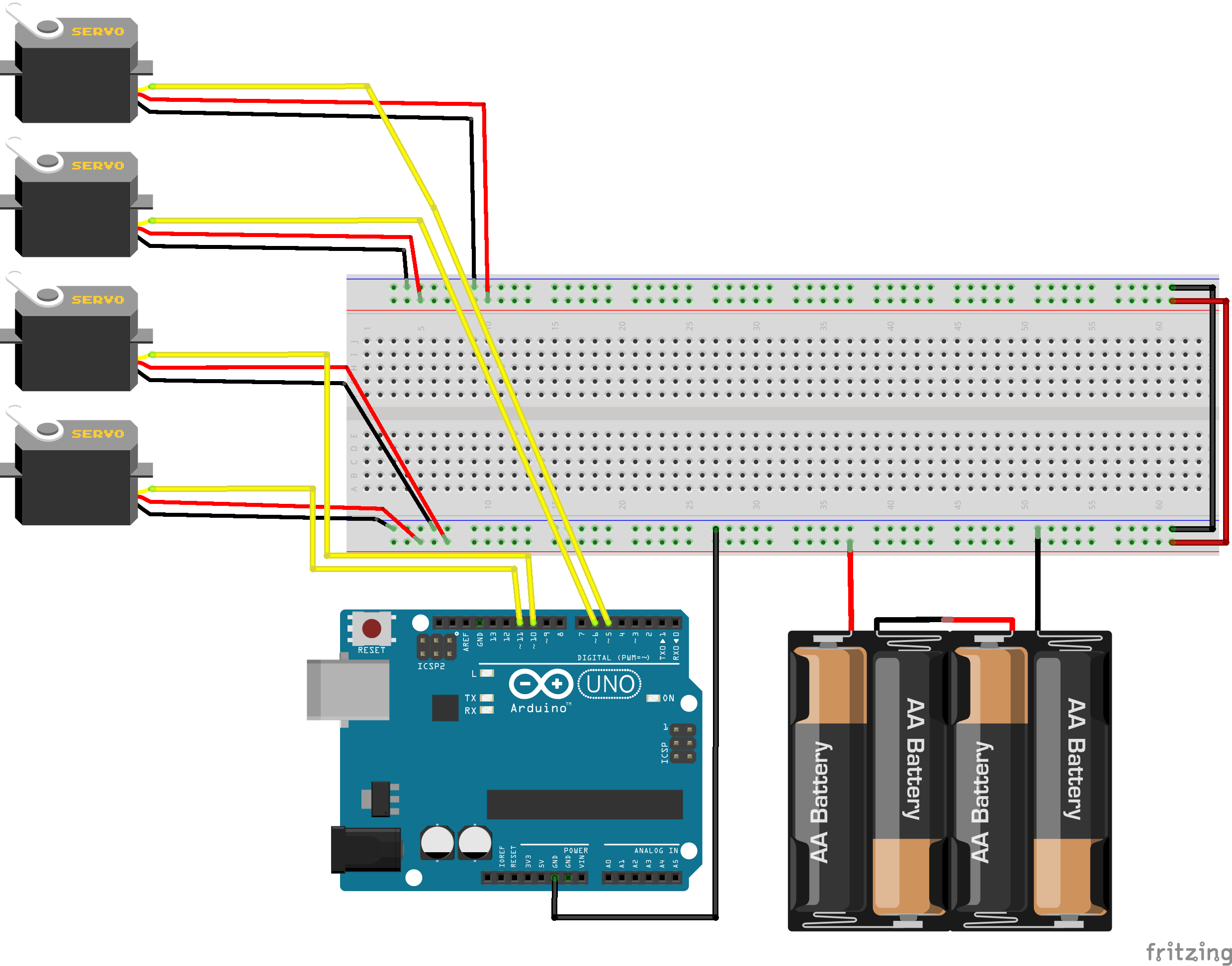
So that's your 3D printed robotic arm, good job :) Now you just need to wire the servos to your Arduino and power them up - for the servos, 4 AA batteries should be enough, you need only 6 Volts. The Arduino you can power it from your computer or from a 9V battery.
1) With your PC:
You will need a calibration code (is in the code section), to test how the robotic arm works and if the servos are mounted well (for example I put my servo was near the 180° and it couldn't go back, only forward). The easiest way to test that is with your laptop or PC. The arduino board can be connected to the computer with through a USB port.How to wire it you can find in the schematics section.
You can write a custom program who executes a certain action, or a program where you can insert values. The Arduino processes them and the servos move.
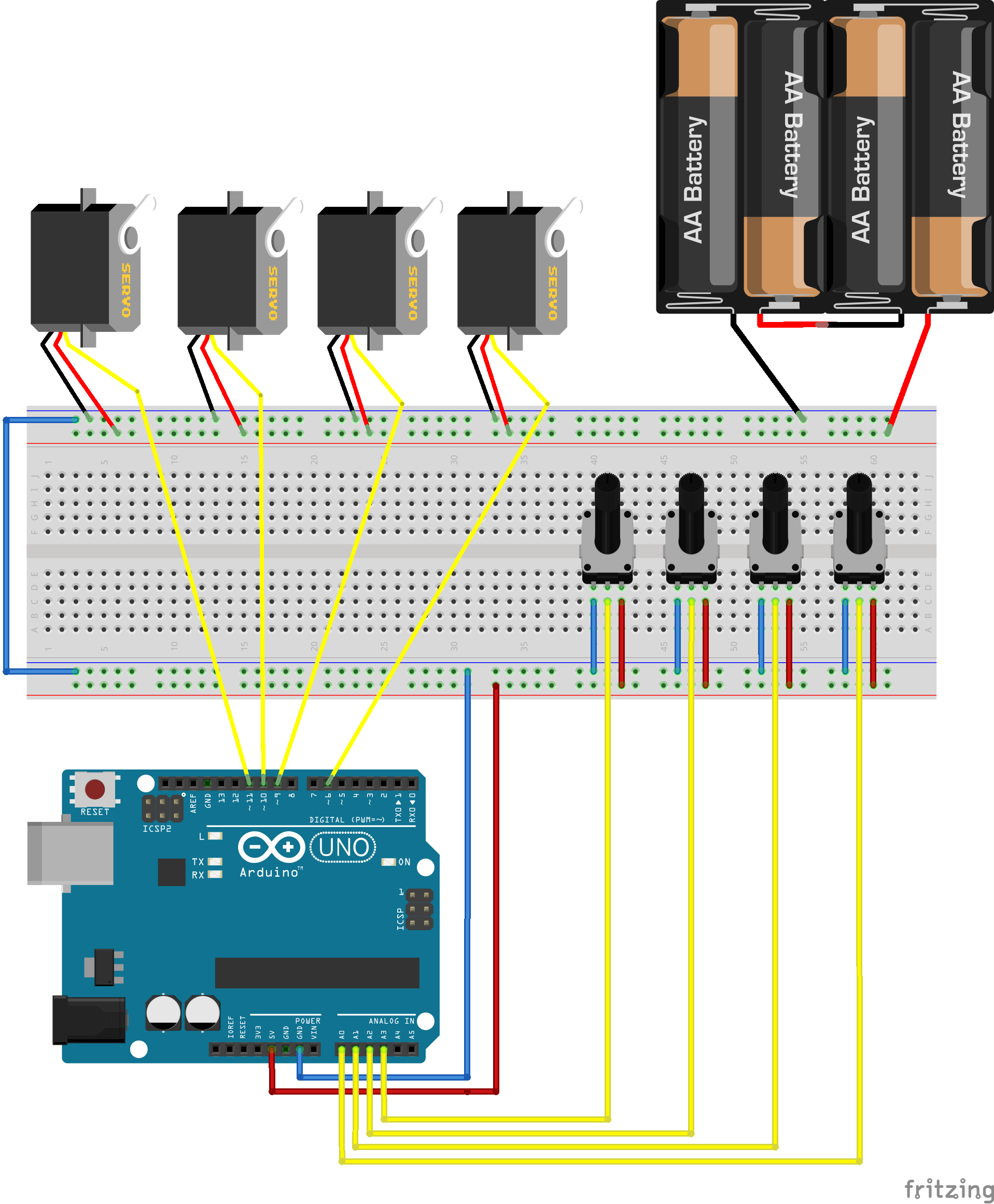
2) With potentiometers (100k or 10k):
To use the robot, you need to figure out how it's movements work,more precisely the 2 principalaxis. It can go up and down, forward and backward, but to perform a process by which it takes an object and do something with it, it becomes more complex.
The easiest way to understand how the robotic arm works, is to use the robot with potentiometers. They are easy to use and they need a short code (found in the code section).
3) With your phone (and HC-05 Bluetooth module):
Of course, to use your phone to control the robot might be the best choice. But this is where things get hard. You are dealing with both serial communication and the creation of an Android app for your phone to act as a remote control.
Feel free to use and improve this project :)
Circuit design with potentiometers


Comments