

Hardware components | ||||||
 |
| × | 1 | |||
| × | 1 | ||||
| × | 1 | ||||
| × | 1 | ||||
| × | 1 | ||||
| × | 2 | ||||
| × | 2 | ||||
| × | 1 | ||||
 |
| × | 1 | |||
| × | 2 | ||||
 |
| × | 4 | |||
Software apps and online services | ||||||
 |
| |||||
| ||||||
| ||||||
 |
| |||||
Hand tools and fabrication machines | ||||||
 |
| |||||
 |
| |||||
Line following robots are one of the most simplistic types of robots that performs a simple task: tracking a black or a white line on a white, respectively on a black surface. In a competition of this type, the added challenge is that the robots have to compete against time, and the fastest wins the competition. Thus, it is a problem of control and accuracy, especially at narrow curves, but also a problem of speed.
So, I wanted to participate in a similar competition, with a robot entirely designed by myself. After researching for some months how these models work, I managed to come up with an acceptable model, which won 4th place in the RoboTEC competition (Romania). Certainly, it can be greatly improved, in terms of the code, as well as the design itself.
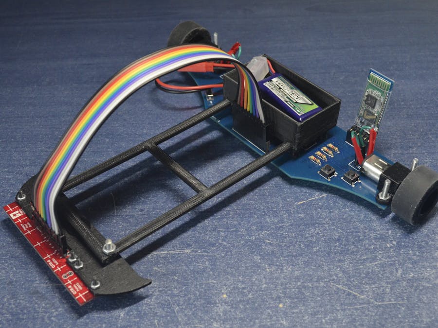
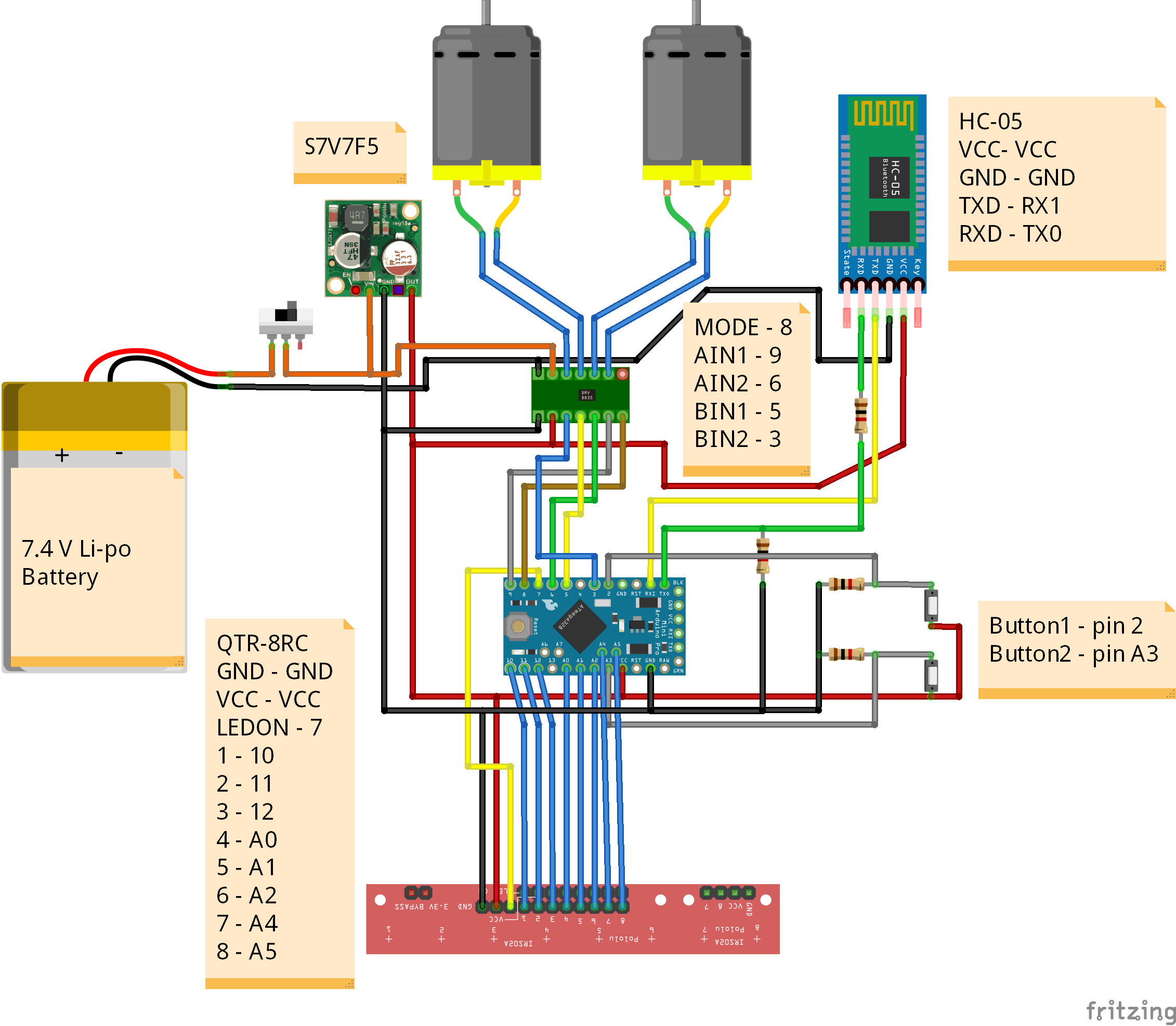
1. HardwareIn this project, I used all the components shown in the Hardware section. In addition, I used a custom PCB sketched by me, which replaces the breadboard and the enormous amount of wires. Finally, I designed 3D parts that connect all the components and thus compose the robot (Figure 1).
As for the power source, I have used a 7.4 V 300mAh LiPo battery. It supplies directly the DRV8835 motor-driver and the 5V step-down voltage regulator, which provides a stable 5V to the microcontroller. The only downside of these LiPo batteries is that if the power drops below half, you are no longer able to charge them. The Arduino Pro Mini has its voltage regulator (with an input ranging between 5 - 12 V), so the voltage regulator can be optional.
I have used two Micro Metal Gearmotor HPCB 6V from Polulu, with a 10:1 gear ratio and 3000 RPM. You can find more about this section of motors on the Polulu link: https://www.pololu.com/category/60/micro-metal-gearmotors.
2. Planning the design of the robotFirst of all, I made this robot with the thought that it will have to respect certain rules of the competition - the robot must not have dimensions higher than 30x30 cm and the curve radius of the track must be at least 7.5 cm - some examples of the tracks I have used for testing can be seen in Figure 2).
I designed it as a "racing car", with 2 motors in the back and a ball caster in the front. I put the QTR-8RC sensor array in the front of the robot so that the ball caster will always be on the line (Figure 3).
Here comes the main problem: what dimensions should the robot take, so as to find a balance between speed and the ability to take the curves without leaving the track. For my first model, I didn't realize how narrow the curves were, and the robot couldn't take them off the track. The only option I had left was to implement an algorithm in which the two motors rotate inversely to each other. Thus, the robot can make a 180 degree without changing its position, but only the orientation. Here comes the main problem: what dimensions should the robot take, so as to find a balance between speed and the ability to take the curves without leaving the track. Even so, the speed at which the robot had to take those curves was far too low, so I reduced the element that holds the PCB to the ball caster (in Figure 4).
If you want to watch a code development from zero that I made for this robot (which explains all the wiring, hardware and how to combine everything to make a functional autonomous line follower):
To use the QTR-8RC reflectance sensor array within an Arduino project, you must first install the specific library. You can search in "Manage Libraries" for "QTRSensors", or, if it doesn't work, open this link: https://www.pololu.com/docs/0J19/all. It provides the steps on how to install the library and documentation about how the sensor works.
Once installed the library, there are a few things that need to be mentioned:
- you can either calibrate the robot and then read the values of the sensors which depend on the initial values from the calibration or read the raw values of the sensors. The first case will be more accurate. If you search in File > Examples > QTRSensors, you will find an example for both cases.
uint16_t position = qtr.readLineBlack(sensorValues);- with this line of code, the sensor array will return the position of the black line. It can be between 0 and 7000. If the position is 3500, it means the sensor array is on the centre of the line
for (uint8_t i = 0; i < SensorCount; i++)
 {
   Serial.print(sensorValues[i]);
   Serial.print('\t');
}- if you want to access a particular sensor from the sensor array, you can call a loop function or simply call sensorValues[anumberfrom0to7]. It won't work if you didn't call first the qtr.readLineBlack(sensorValues);
- in my final program, I didn't make the calibration automatic. So, at the beginning of the program, during this phase, you should expose each reflectance sensor to the lightest and darkest readings they will encounter. For example, if you are making a line follower, you should slide the sensors across the line during the calibration phase so that each sensor can get a reading of how dark the line is and how light the ground is. Improper calibration will result in poor readings.
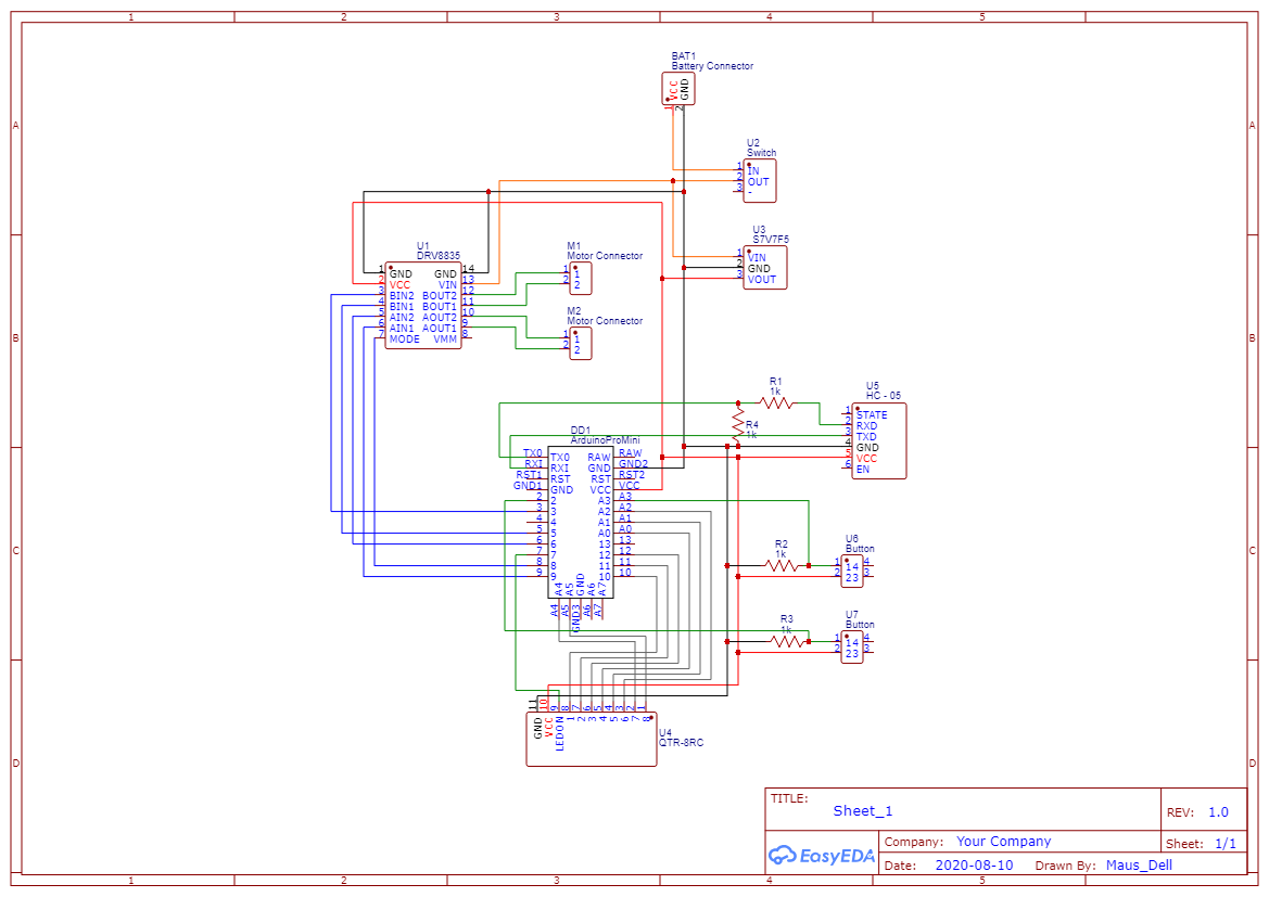
In this project, I wanted to do something different and try not to use breadboard and wires in making the robot. So I mounted all the components on a PCB, to save space and not have problems with the connections. Designing this wasn't so hard. First I made the schematic circuit with EasyEDA. Then, this software has a feature that can convert the schematic into a PCB, so making the connections between the components will be more simple. I only had to outline the PCB, place the components inside the outline and then wire them (you can do it manually or automatic with an auto-router). I ordered 5 pieces directly from their website (the PCB stores in my country asked me to pay four times the normal price for them) and the delivery was in 3 weeks. Then I soldered some of the components directly on the PCB and the other components with a female header on the PCB - the HC-05 and the wires from the sensor array (so that way I could reuse and remove them).
The other components (the battery and sensor support) I made from 3D printed components. I used CAD software (SketchUp) and then for each part I imported one as an STL file. After that, I printed them at an electronics store. I had few problems with the screws because the holes were too small or the 3d printed parts came over them. I used M3X16 screws for the motors brackets and the battery and sensor support, and M2X10 screws for the ball caster.
!!You might want to review the STL of battery support because it might not be good for another battery. It can be bigger or the wires that connect the battery might not fit in the hole made especially for them.
The line following algorithm is quite simple. If the position is higher or lower than 3500, then the robot must turn left or right.
But if we put this in a loop, the robot will oscillate until it eventually gets off track. And this is where PID control comes in handy. In practical terms, it automatically applies an accurate and responsive correction to a control function (Wikipedia). This means that the robot will no longer oscillate and will be able to take different types of curves at different curve radius without getting off the line. To make it easier to understand the program, we will use an integral called error. It can be both positive and negative.
int error = 3500 - position;The distinguishing feature of the PID controller is the ability to use the three control terms of proportional, integral and derivative influence on the controller output to apply accurate and optimal control (Wikipedia). But that's not all. For each term, it corresponds to a constant, Kp, Ki and Kd, that must be adjusted so that the robot can follow a line without oscillating or slowing down or getting off the track.
- Here, the proportional term is the error. It directly controls how to take the curves - if Kp is a small value he will take the curves easier (he will go almost straight); if it is a large value it will take the curves suddenly (either it will oscillate on a straight line, or it will take the curve too tight and it will leave the track).
int P = error;- The integral term accumulates all errors. The integral term seeks to eliminate the residual error by adding a control effect due to the historic cumulative value of the error. When the error is eliminated, the integral term will cease to grow. This will result in the proportional effect diminishing as the error decreases, but this is compensated for by the growing integral effect (Wikipedia). In other words, it helps the robot stop oscillating. But at a Ki that is too high, it will do the opposite.
int I = I + error;- The derivative term calculates the current error and the last error. When the robot suddenly hits a tight curve, this value will be high and will force the robot to take the required curve. The more rapid the change, the greater the controlling or dampening effect (Wikipedia). At a Kd too small, this value might not take place. At a Kd too high, it can give errors to the whole program and the robot can oscillate, run very slowly or take very narrow curves that don't even exist.
int D = error - lastError;
lastError = error;
In the end, the equation of speed that will be applied to the motors will be:
float motorspeed = P*Kp + I*Ki + D*Kd;
int motorspeeda = basespeeda + motorspeed;
int motorspeedb = basespeedb - motorspeed;
//where basespeed is the speed of each motor when the robot goes in a straight line - 100 or 150
The whole point of this algorithm is finding the 3 constants. They can be anything. For example, for my robot Kp is 0.07, Ki is 0.0008 and Kd is 0.6. You can change their values every time in the program, or you can put a Bluetooth module in which you can control these values directly from the phone.
6. Bluetooth controlIn this project, I made my robot with an HC-05 Bluetooth module to make it easier for me to find those values. I will give an Arduino file where I did the control via Bluetooth, as well as the APK file (located in the schematics part). The PCB schematic also contains the Bluetooth module.
I used MIT App Inventor because I can make this type of apps fast. Although, it is not the best. First, you design the look of the app and second you block-code it.
The idea of how I made the connection between the Arduino (HC-05) and the phone is simple. Because I couldn't send a value higher than 255 (I only could send one byte), I had to do it in such a way that for each instruction (for example the change of sliders) I first sent a number that represented the instruction (1 for Kp, 3 for Ki, 5 for Kd and 7 for the buttons). But that means that the constants will be between 0 and 255. And for example for my robot Ki is 0.0008. So I made a second value for each constant(multiP, multiI and multiD), that divides by a power of 10 the constants. For example, the Arduino receives the values 1, 55 and then 2, 2. That means the Kp is first 55, then multiP is 100. At the end Kp is 55 / 100 = 0.55. Because Ki is the smallest number and has 4 decimals, the slider of the multi takes a number between 0 and 5 (10^5 = 100000). The code that has in its name (+ Bluetooth communication) is made especially for phone communication.


_3u05Tpwasz.png?auto=compress%2Cformat&w=40&h=40&fit=fillmax&bg=fff&dpr=2)
Comments