

Hardware components | ||||||
 |
| × | 1 | |||
 |
| × | 1 | |||
 |
| × | 1 | |||
 |
| × | 1 | |||
 |
| × | 1 | |||
| × | 1 | ||||
 |
| × | 1 | |||
 |
| × | 1 | |||
Software apps and online services | ||||||
 |
| |||||
 |
| |||||
 |
| |||||
This project has primarily three functionalities i.e. to monitor the light intensity on the plants using an LDR, to send an SMS whenever there's a sudden spike in the intensity and to alert the gardener using the buzzer. So, one can sit at home and monitor his plants back at the garden or alert a lazy gardener! The LDR will continuously monitor the light intensity and if there's a sudden increase/drop in the light intensity, it is detected using Z-score analysis and an SMS will be sent to your phone. You can then switch on the buzzer by just pressing a switch and the buzzer present near the plants will alert the gardener.
2.DEMONSTRATIONAlert Notification on Phone via Twilio:
The detailed working of the 3 steps are given below:
3.1. LDR light monitoring:The resistance of an LDR varies inversely with light, i.e., the resistance decreases as the intensity of light falling on the LDR increases.
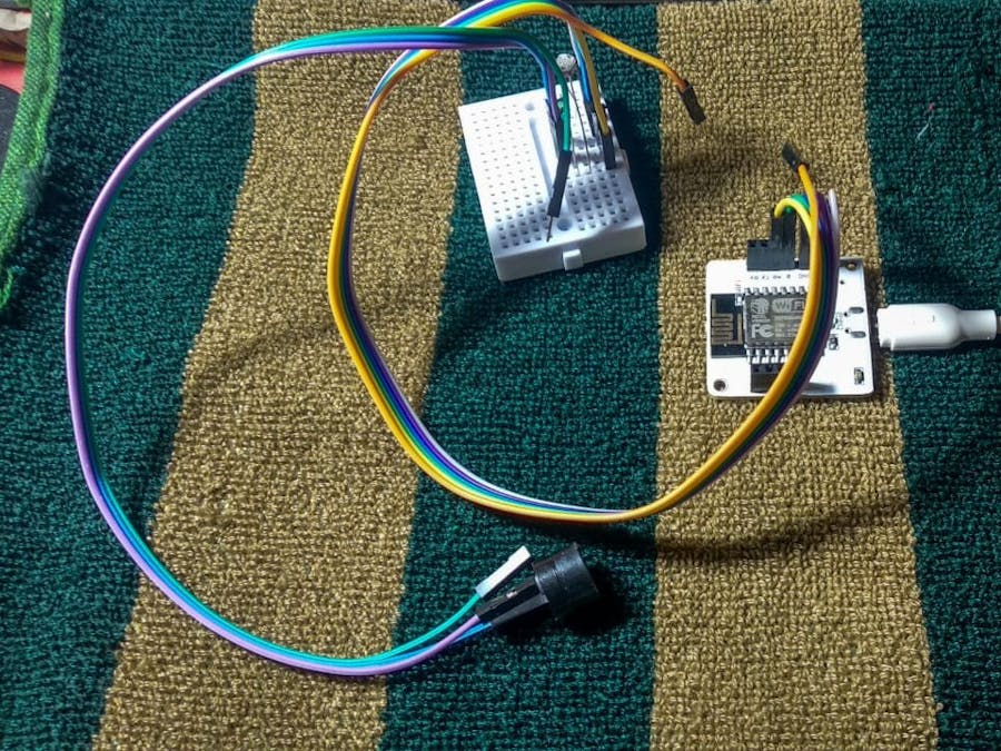
The input from the LDR is taken at analog pin A0 and the output to the LED is written at digital pin 0. LDR terminals don't have polarity. The power supply to the LDR is given using 3.3V pin of the bolt module. The resistance across LDR changes with change in light intensity falling on it.
Since the Bolt Module cannot read resistance values, but it can read voltage values, hence a voltage divider circuit is made and the input to the Bolt module is the voltage across 10k resistance (since it is connected between an LDR terminal and ground) which depends on the resistance across LDR
(There is no positive or negative for this and the 10k Ohm resistor)
Step 1: Insert one lead of the LDR into the Bolt Module's 3v3 Pin.
Step 2: Insert other lead of the LDR into the A0 pin.
Step 3: Insert one leg of the 10k Ohm resistor into the GND pin.
Step 4: Insert the other leg of the resistor also into the A0 pin.
All the above steps are done using Male/Male jumper wires and Male/Female Jumper wires and a breadboard.
The python coding for this project has been done in Ubuntu (Linux). Before we start coding of the automating controlling of LED brightness in python, we need to make a configuration file which will have the specific keys for each user/device. We will import this file in our main code and use the various attributes. The advantage of this is that each user will only have to change the contents the configuration file to use the product.
The following is the configuration file (named as conf.py):
SSID = 'You can find SSID in your Twilio Dashboard'
AUTH_TOKEN = 'You can find  on your Twilio Dashboard'
FROM_NUMBER = 'This is the no. generated by Twilio. You can find this on your Twilio Dashboard'
TO_NUMBER = 'This is your number. Make sure you are adding +91 in beginning'
API_KEY = 'This is your Bolt Cloud account API key'
DEVICE_ID = 'This is the ID of your Bolt device'
FRAME_SIZE = 10
MUL_FACTOR = 3Z-score analysis is used for anomaly detection. It is used to monitor if there's a sudden spike in the readings w.r.t the bounds(upper and lower). These bounds are calculated using the input values, frame size and multiplication factor. The frame size is the minimum number of input values needed for Z-score analysis and the multiplication factor determines the closeness of the bounds to the input values curve.
Given above is the formula to calculate the bounds. Here the input is represented as 'Vi', 'r' denotes the frame size and 'C' is the multiplication factor. Firstly we calculate the mean (Mn) of the input values (for every new input, the mean is calculated again). The variation of each input value (from the mean) is given as (Vi - Mn)^2. The Z-score (Zn) is calculated as shown above ( square root of the mean of the variation of each input value multiplied by the multiplication factor). The bounds are represented as 'Tn' and the upper bound is calculated as (Vi + Zn) and the lower bound is calculated as (Vi - Zn).
The frame size and multiplication factor are determined using trial-and-error method.
3.2. Getting SMS alert via Twilio on your phone:Twilio is a third-party SMS functionality provider. It is a cloud communications platform as a service (PaaS) company. Twilio allows software developers to programmatically make and receive phone calls and also send and receive text messages using its web service APIs.
3.2.1.Creating an account on TwilioStep 1: Open https://www.twilio.com/ in browser.
Step 2: Click on Get a Free API Keybutton to sign up.
Step 3: Fill all the necessary details in SIGN UP form.
Choose SMS plan and python language for the project.
Step 4: To verify they will ask for your phone number. Choose India as an option in the dropdown and then enter your phone number.
Step 5: Now, you will need to give a name for your project. I have given the name as My Project. Click on "Continue" once you have entered the project name.
Step 6: You can view the Account SID and Auth token on this page. The Auth token is not visible by default, you can click on "view" button to make the Auth token visible as shown below. Copy both and save them somewhere securely.
Step 7: Click on Get a number button.
Step 8: Then a popup will appear. Click on Choose this number button.
Step 9: Then a popup will appear which will have the final number. Copy this number and save to notepad for future references.
That's it. You have successfully created the account on Twilio.
3.2.2.Getting SMS alert via Twiliomybolt = Bolt(conf.API_KEY, conf.DEVICE_ID)The above code will automatically fetch your API key and Device ID that you have initialized in conf.py file.
- Now to send an SMS, we will create an object of the same.
sms = Sms(conf.SSID, conf.AUTH_TOKEN, conf.TO_NUMBER, conf.FROM_NUMBER)The above code will automatically fetch your SSID, AUTH_TOKEN, TO_NUMBER and FROM_NUMBER that you have initialized in conf.py file.
Step 1: Take the longer leg of the BUZZER i.e positive leg and insert it in digital pin 0 of the Bolt.
Step 2: Insert the negative leg of the BUZZER into the ground pin of the Bolt.
All the above steps are done using Male/Male jumper wires and Male/Female Jumper wires and a breadboard.
Step 1: Go to cloud.boltiot.com and create a new product. While creating the product, choose product type as Output Device and interface type as GPIO. After creating the product(here:buzzzer), select the recently created product and then click on configure icon.
Step 2: Move to the code tab and write the following code to control the BUZZER.
In the header, we will include a javascript file which has some pre-defined function like DigitalRead, digitalWrite etc already hosted on Bolt Cloud.
(API key and Device name will be auto-initialized by Bolt cloud. Don't have to replace the device name and API key in the above code.)
Step 3: Once you have written the complete code in the editor, give the file name as buzzercontroland in the drop-down select the file extension as html.
Step 4: Now click on save icon to save the code. Now go back to the dashboard by clicking on 'X' icon.
Step 5: In the products tab, select the product created and then click on the link icon. Select your Bolt device in the popup and then click the 'Done' button.
Step 6: Now click on view this device icon to view the page that you have designed. Below is the screenshot of the final output.
Now click on ON button, it will turn the BUZZER on. Similarly, clicking on OFF button will turn BUZZER off.(Remember to remove the sticker on the buzzer before doing the project).
3.4 OUTPUT of ubuntu code for light monitoring.Complete code for light monitoirng is:
import conf, json, time, math, statistics
from boltiot import Sms, Bolt
def compute_bounds(history_data,frame_size,factor):
    if len(history_data)<frame_size :
        return None

    if len(history_data)>frame_size :
        del history_data[0:len(history_data)-frame_size]
    Mn=statistics.mean(history_data)
    Variance=0
    for data in history_data :
        Variance += math.pow((data-Mn),2)
    Zn = factor * math.sqrt(Variance / frame_size)
    High_bound = history_data[frame_size-1]+Zn
    Low_bound = history_data[frame_size-1]-Zn
    return [High_bound,Low_bound]

mybolt = Bolt(conf.API_KEY, conf.DEVICE_ID)
sms = Sms(conf.SSID, conf.AUTH_TOKEN, conf.TO_NUMBER, conf.FROM_NUMBER)
history_data=[]

while True:
    response = mybolt.analogRead('A0')
    data = json.loads(response)
    if data['success'] != 1:
        print("There was an error while retriving the data.")
        print("This is the error:"+data['value'])
        time.sleep(10)
        continue

    print ("This is the value "+data['value'])
    sensor_value=0
    try:
        sensor_value = int(data['value'])
    except e:
        print("There was an error while parsing the response: ",e)
        continue

    bound = compute_bounds(history_data,conf.FRAME_SIZE,conf.MUL_FACTOR)
    if not bound:
        required_data_count=conf.FRAME_SIZE-len(history_data)
        print("Not enough data to compute Z-score. Need ",required_data_count," more data points")
        history_data.append(int(data['value']))
        time.sleep(10)
        continue

    try:
        if sensor_value > bound[0] :
            print ("The light level increased suddenly. Sending an SMS.")
            response = sms.send_sms("Someone turned on the lights")
            print("This is the response ",response)
        elif sensor_value < bound[1]:
            print ("The light level decreased suddenly. Sending an SMS.")
            response = sms.send_sms("Someone turned off the lights")
            print("This is the response ",response)
        history_data.append(sensor_value);
    except Exception as e:
        print ("Error",e)
    time.sleep(10)
The full output is available in the demonstration video. This is a screensnip of the output on ubuntu. The SMS alert is posted above.
Sorry, but I coudn't figure out how to use the Fritzing software as it wasn't downloading and create the schematic diagram. So I tried to draw it and make as easy to understand as possible.
Connecting the bread board and the bolt iot module are the male/male jumper wires.
The different hardwares are connected to the bread board via male/female jumper wires.


Comments