

Hardware components | ||||||
_ztBMuBhMHo.jpg?auto=compress%2Cformat&w=48&h=48&fit=fill&bg=ffffff) |
| × | 2 | |||
 |
| × | 2 | |||
| × | 1 | ||||
 |
| × | 2 | |||
| × | 1 | ||||
 |
| × | 3 | |||
 |
| × | 2 | |||
 |
| × | 2 | |||
| × | 2 | ||||
| × | 1 | ||||
 |
| × | 1 | |||
Software apps and online services | ||||||
 |
| |||||
Hand tools and fabrication machines | ||||||
 |
| |||||
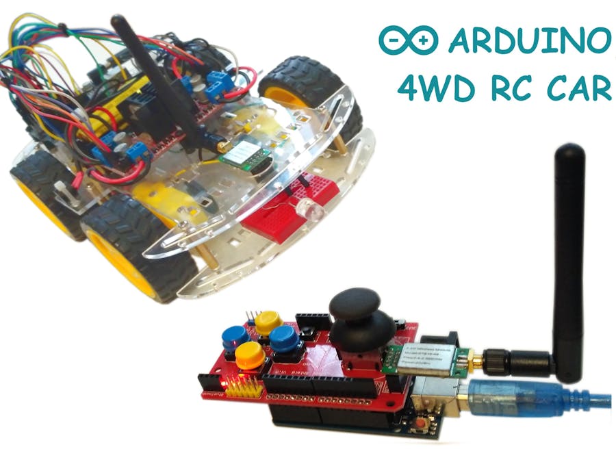
Hi everyone! This is my next project - Arduino 4WD RC Car with Joystick Controller or How easy it is to control an Arduino 4WD Smart Car with an analog Joystick.
This RC joystick controlled car uses NRF24l01 as the transmitter and reciever. It has a range up to 1 kilometer in open space. Also is very simple and easy to make.
1. Joystick ControllerComponents for Joystick:
Joystick shield sits atop your Arduino and turns it into a simple controller. 7 momentary push buttons (4 big buttons, 2 small buttons, and a joystick select button) and a two-axis thumb joystick gives your Arduino functionality on the level of the old Nintendo controllers. This unit also offers Nokia 5110 LCD and nRF24L01 interfaces.
Features:- nRF24L01 Interface
- Nokia 5110 LCD Interface
- Bluetooth Interface
- I2C Interface
- Compatible with Arduino
- Operating voltage 3.5V or 5V
Actually, it is labelled as BTE16-49 - nRF24L01+RFX2401C +PA+LNA wireless communication modules with antenna shielding case 2.4GHz 20dbm 1000m.
Characteristics specified by the seller:
- 2.4GHz global open ISM band, license-exempt use
- the maximum operating speed of 2Mbps, efficient GFSK modulation, transmission of audio, video
- 125 channels, to meet the multi-point communications and frequency-hopping communications needs
- the address of the built-in hardware CRC error detection and point-to-multipoint communication control
- working voltage 3.0-3.6V, the transmit power 20dBm (VDD = 3.3V)
- the external 2.4GHz antenna
- 2.54mm pitch pins, fully compatible without the amplifier module interface, easy to replace enhance distance
- transmission distance up to 1000 m
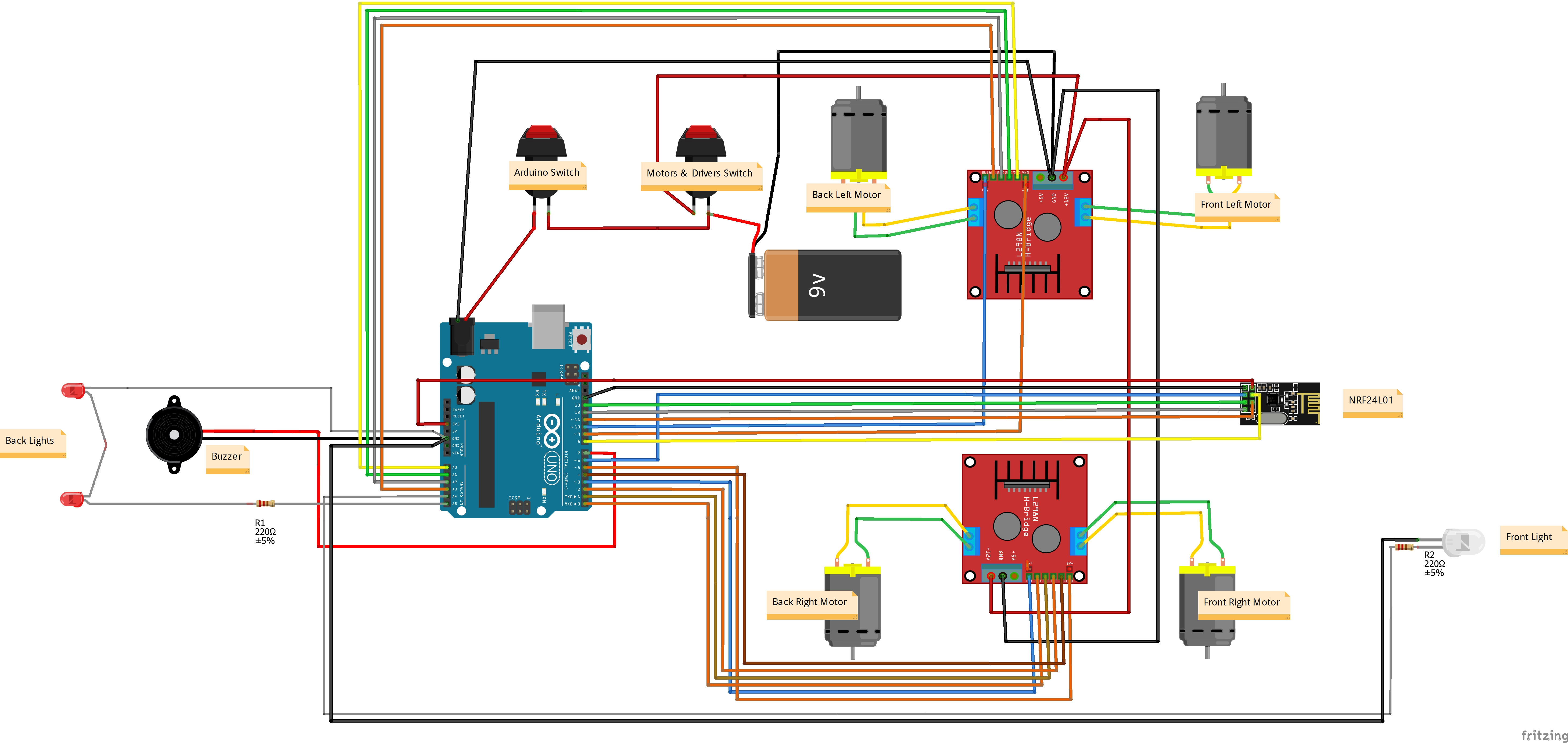
Joystick Shield has 4 big buttons + 2 small buttons + joystick select button and a two-axis thumb joystick (X-axis from 0 to 1023, Y-axis from 0 to 1023) The shield sits on top of your Arduino and turns it into a simple controller. In my sketch Button Up is for Buzzer (horn), Button Right - front light (LED + resistor 200 Ohm), Button Left - back ligts (LEDs + resistor 200 Ohm). Other buttons are not used.
Joystick Testing:
Idle state: X=499, Y=502, Up=1, Right=1, Down=1, Left=1
Make connections as in the wiring diagram image above.
Note: before uploading the code you have to disconnect jumper wires from Arduino Uno board (pins 0, 1).
That it once you made all steps properly Car is ready to go!
After powering Arduino Car and Joystick controller you can use the Joystick to control the car by moving the Joystick forward and backward the car will move in the Forward or Backward direction, and moving the Joystick left and right will make the car turn left and right.
Stay tuned!


_3u05Tpwasz.png?auto=compress%2Cformat&w=40&h=40&fit=fillmax&bg=fff&dpr=2)


Comments