

Hardware components | ||||||
 |
| × | 1 | |||
 |
| × | 1 | |||
 |
| × | 1 | |||
 |
| × | 1 | |||
Hand tools and fabrication machines | ||||||
 |
| |||||
Ever since I started playing around with ESP modules I wanted to measure weather conditions in multiple location at home, friends, etc. The best way to achieve that would be to build a station that gathers various environment parameters and publishes them somewhere. That is what I've done. The very first prototype was done using ESP-1 module, DHT-11 humidity sensor and BMP280 breakout board. The station publishes gathered data to a MQTT broker from where it can be further gathered and analysed.
Basically the operation of the station is as follows: the station will try to connect to configured multiple Wifi networks and if no such were found, will try open networks. Then it will connect to MQTT broker and announce telemetry data until 30 seconds elapses. In that case it will go to deep sleep for 30 minutes and the process starts over.
During development and playing around, three variants were born: OLED, E-Paper and Headless.
The source code for the station is here. More details on my blog. There is a second part of this writeup, and I even gathered up the courage to post it on Tindie :)
Features- mDNS
- OTA
- WebUI configuration
- Low Power operation
- Connect to free wifi or one of configured networks
- MQTT Pub/Sub
- Report temperature
- Report relative humidity
- Report air pressure
- Report battery voltage
- Monitor and display several other station telemetry
- Headless
- OLED display
- E-Paper display
- Configure Wifi networks via MQTT
- Configure station name via MQTT
- Configure station names to be monitored via MQTT
- Persistent telemetry MQTT messages
Each station variant tries to connect to either open wifi or one of configured wifi networks giving priority to configured networks. After that it tries to connect to a configured MQTT broker. Once initial telemetry data is available, starts to publish telemetry data to MQTT broker every 1s. After 30s of bootup will go to deep sleep. After 30 minutes will wake up and repeat the cycle.
OLED/E-Paper variants also display gathered telemetry data. Calculated power demand is around 1mAh and can be lowered by reducing time spend awaken and removing LEDs from ESP module. Also higher resistor value for voltage divider could be used.
Configuration of the station is done via MQTT messages. E.g. to set a name for device "18:FE:34:A7:05:1A" one should publish a string e.g. "Balkony" to "18:FE:34:A7:05:1A/name". E-Paper variant is a little bit different. You can specify up to three other station names to display by separating names with a space, e.g. "paper room Balkony closet" to "18:FE:34:A7:05:1A/name".
HeadlessDHT-11 and BMP280 modules can be seen in the photo, as well as Li-Ion battery and ESP-1 module. I had to solder wires directly GPIO16 and ADC of the ESP chip. It's not that hard as it looks, all that is needed - a little bit of flux, steady hands and thin soldering iron :)
By the way, since there are very little GPIO pins available, I use RX/TX pins for I2C interface. I2C devices seem not to mind an initial burst of bootup information. I never changed the pins for ESPWeather variants that use ESP12 modules.
OLEDAfter some time I grew tired of checking up my phone for MQTT readings just to check what is going on at my desk, so I've built an OLED variant. Since I already have I2C interface for BMP280 sensor, all I did was hook up an OLED screen to SDA/SCL and thus OLED variant was born. Also I had to add some code to support that, of course, and since I had plans for other display types support in the future, I've created a neat C++ interface to easily swap display types during compile time.
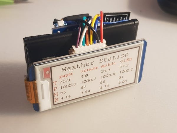
E-PaperAs I was starting to accumulate a number of weather stations put in different places and I found smartphone MQTT client app invonvenient, I decided to use one of my Waveshare 2.13" E-Paper displays. I figured since it is ultra low power the whole station should last a very long time between charges. The display width allows to display data gathered from four stations.
For this particular station I had to use ESP-12 module instead of ESP-1 as the latter lacks adequate number of GPIO pins :)
This station does the following - connects to the MQTT broker, subscribes to station announcements channel and catches messages from preconfigured station names and displays them after all the readings are gathered. Just before going to deep sleep.
ConstructionDHT11 and BMP280 modules are used in this station for prototypes. BME280 or even BME680 will be used in production. SSD1306 and 3 colour 2.13" E-Paper HAT are used for OLED and E-Paper variants respectively. For E-Paper prototype Wemos D1 mini was used and later replaced with standalone ESP-12F module.
For battery management I used a TP4050 micro-usb module with protection circuitry. If one has Lipo/LiIon batteries with protection in possession, then protection-less charging boards can be used.
I also added a 6V solar panel so I could start measuring outside temperature without worrying about the battery.
OLED variant in the above picture does not use any charging circuitry as it is meant for always-connected (or battery-pack) usage. However please note, that most battery packs will disconnect the battery from the station once it goes into deep sleep mode due to extremely low current consumption.
Cases for these can be 3D printed.
- Rx is SCL
- Tx is SDA
- GPIO 2 is 1-Wire interface for DHT11
- GPIO 13, 14, 15, 5, 12, 4 are for EPD signals: DIN, CLK, CS, DC, RST, BUSY respectively
- TOUT or ADC is for battery monitoring and connected to battery input via 1/10 voltage divider (ADC can measure up to 1.0V, so this scale factor is quite convenient)
- sourced on Ebay: DHT11 for ESP-1S module, BMP280 board, TP4050 lipo micro-usb charger board, SSD1306 and 2.13" RPI-Zero E-Paper HAT (Waveshare)
- LiIon Batteries from various dead cell phones and cheap Chinese video registrators
I use 100k trim pot directly across battery connector to the DH11 board, trim it to 1/10th of the battery voltage and solder the center tap to a TOUT pin right to the ESP8266 chip. I suggest flashing the ESP-1 module before soldering, so that the wire wouldn't be stressed too much. Discrete resistors for voltage divider can be seen in some the photos - this is because I ran out of trim pots:) And the dividing factor is not really precise, since I did not have 90k resistors and opted out for 2x51k + 10kx1k resistors. For the prototypes I am only interested in monitoring approximate voltage drop for the batteries and approximate point when DHT11 fails to provide meaningful readings.
At about 2.80V of battery voltage DHT11 library returns nan. This voltage is even too low for ESP, but surprisingly it survives until 2.65(minus voltage drop across ldo).
Deep Sleep functionFor waking up from Deep sleep GPIO 16 must be connected to RST. So more fine soldering skills are required in case of ESP-1. ESP-12 is more forgiving in that regard.
Reducing current consumptionI've measured 1.8ma current in deep sleep. That means that the station sleeps for 30 minutes with 1.8mA current consuming 1.8mAh(I assume it never goes away). During all the communication and measurements somewhere around 70-90 mA are flowing to the ESP. So let's say it's 75mA for 30s. That translates to 0.625mAh. Therefore 800mAh battery would last a long time (about 13 days). Sadly, the batteries I am using in the photos are pretty much dead and charge up to around 75-120mAh. Which lasted for about 40 hours which confirms current consumption measurements and rough calculations to a degree.
That was with two LEDs being constantly lit and an onboard regulator. Which I am surprised by, by the way. One can always remove those buggers, but I figured that with solar panel the station would run almost indefinitely and would have plenty of run time for home usage with a 800mAh battery. By removing the blue LED(that is constantly lit. On most boards that is red LED) current drops to ~400uA during deep sleep and the dead'est battery still runs for 4 days already at 3.75V.
You can find more information and pictures on my blog.
.


_3u05Tpwasz.png?auto=compress%2Cformat&w=40&h=40&fit=fillmax&bg=fff&dpr=2)
Comments