

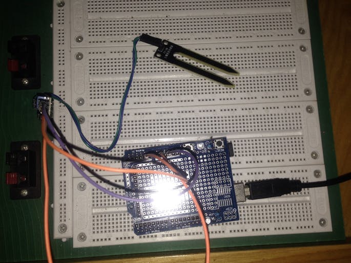
There are a total of four pins for the soil moisture sensor (you can redeem it free from PCBWay):
- VCC pin: power supply positive
- GND pin: power negative
- A0 pin: Output the analog voltage valueof soil moisture sensor, range from 0 to 1023
- D0 pin: Output the switch value of soil moisture sensor, 0 and 1,
Use a simple code to test it. Check the output value of the A0 pin. The program as follows:
const int buttonPin = A0;
int inputValue = 0;
void setup() {
pinMode(buttonPin, INPUT);
digitalWrite(buttonPin, LOW);
Serial.begin(9600);
}
void loop() {
inputValue = analogRead(buttonPin);
Serial.println(inputValue);
}
There is a large flowerpot in my home. I put the soil moisture sensor in the flowerpot to test it. A picture of the flowerpot is shown below. The soil moisture sensor will insert in different positions during the test.
Finally, I collected more than 8000 data, put these data into matlab, get the following graph:
The output of A0 pin is 1023 when the soil moisture sensor isn’t insert into the flowerpot.
When the soil moisture sensor is inserted into a certain position within the flowerpot, the output value of the A0 pin rapidly drops to a certain stable value. Then pull out the soil moisture sensor and insert it into other positions of the flowerpot. At this time, the A0 pin outputs different analog values depending on the humidity in different positions.


Comments