


Hardware components | ||||||
 |
| × | 1 | |||
 |
| × | 1 | |||
 |
| × | 1 | |||
 |
| × | 1 | |||
| × | 1 | ||||
 |
| × | 1 | |||
Software apps and online services | ||||||
 |
| |||||
| ||||||
| ||||||
Here we’ll walk through the complete process of building a smart irrigation device - from hardware wiring to a fully working control logic running on the microcontroller.
You’ll learn how to publish real-time telemetry, handle server-side RPC commands, and connect the device to ThingsBoard dashboards for remote monitoring and control using the Arduino ThingsBoard Client SDK.
All device logic is implemented on an ESP32 in C++ (Arduino framework).
PrerequisitesBefore we begin, let’s review the full list of hardware, software, and Arduino libraries used in this project, along with the links you will need.
SoftwareFor the software part, we use C/C++ as the device runtime, Arduino IDE as the development environment together with the Arduino IDE ESP32 Dev Module Boards manager extension, and ThingsBoard as the device management platform.
To send telemetry and handle communication over MQTT, the project relies on the ThingsBoard Arduino Client SDK.
HardwareFor the hardware setup, we use an ESP32 development board, the DFRobot Gravity Analog Capacitive Soil Moisture Sensor (SEN0193), a 1-channel 5V relay module to switch the load, and a 3–6V submersible mini water pump. We also use a solderless breadboard, jumper wires (male-to-male / male-to-female depending on your modules), and an external 5V power source for the relay and pump wiring. All device logic in this guide is implemented in C++ using the Arduino IDE (Arduino framework).
Arduino IDE LibrariesTo start working we need to install ThingsBoard Arduino SDK library and other libraries required for data communication.
For now, let’s briefly look at the purpose of each library used in the project:
- ThingsBoard - library for Arduino to connect with the ThingsBoard IoT platform over MQTT.
- TBPubSubClient - a client library for MQTT messaging.
- ESPMQTTClient - a library that provides a wifi and MQTT connection to an ESP8266/ESP32.
- ArduinoJson - a simple and efficient JSON library for embedded C++.
- ArduinoHttpClient - easily interact with web servers from Arduino using HTTP and WebSockets.
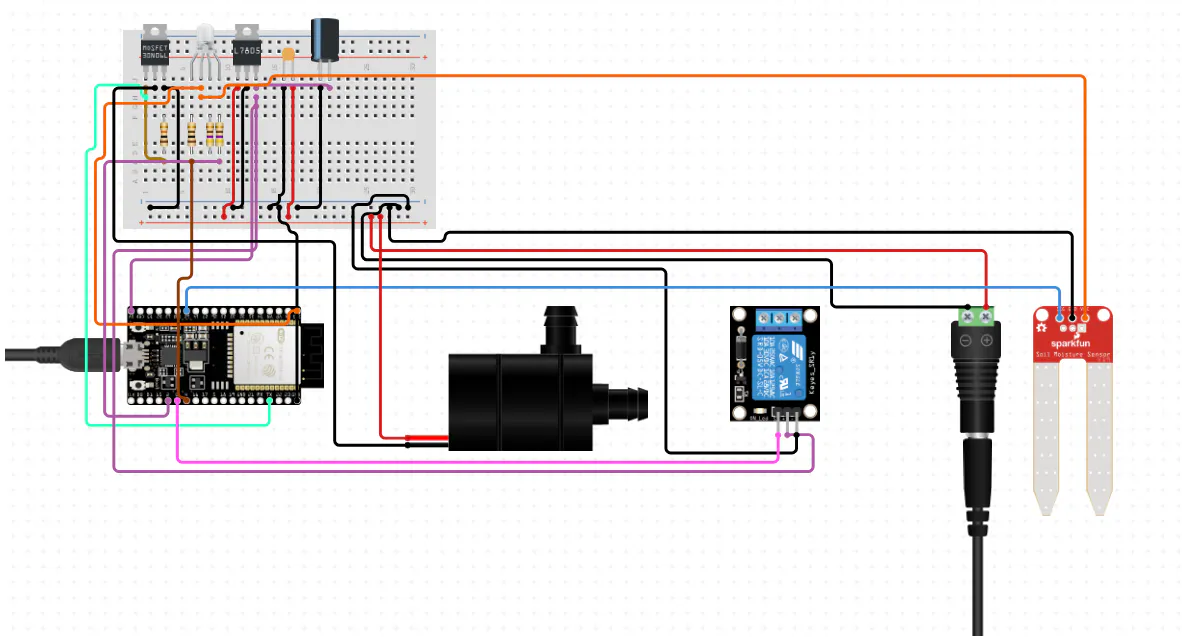
For connection simplicity of all required hardware components, we are attaching the connection schema below with its detailed description.
The ESP32 is powered via a USB Type-C cable, which is used both for power and for uploading the firmware. The soil moisture sensor is connected with three wires: VCC, GND, and analog output, which is wired to an ESP32 ADC pin (GPIO36 in this project) to read the soil moisture level.
A 1-channel relay module is connected to GPIO27 and is used to switch the water pump, which is powered from an external supply. An RGBLED is connected to three ESP32 GPIO pins through 220 Ω current-limiting resistors, which protect both the LED and the microcontroller pins.
In this project, the LED acts as a visual indicator of the soil state: red for dry, green for normal, and blue for wet. During operation, the ESP32 reads the sensor value, determines the current moisture state, updates the LED color, and turns the pump on or off through the relay when watering is needed.
ThingsBoard PreparationBefore starting, make sure that you have local ThingsBoard instance up and running or use ThingsBoard Cloud. In this step, we will create a device on the ThingsBoard platform and obtain the access token required to connect our physical ESP32 device to the platform.
To complete this step, follow the instructions below:
- On the ThingsBoard platform, open the Devices page. By default, you navigate to the device group “All”. Click on the “+” icon in the top right corner of the table and then select “Add new device”.
- Input device name (it should be called “irrigation device”) and click the “Add” button.
- Click on the device row in the table to open device details. Click "Copy access token". The Token will be copied to your clipboard.
ESP32 development boards do not come with your Arduino sketch preinstalled, so you need to prepare the board in the Arduino IDE before uploading the code. This includes installing ESP32 board support through the Boards Manager and selecting the correct ESP32 board model and serial port in the IDE.
After completing this setup, the ESP32 will be ready to compile and run your Arduino C++ firmware.
Code ExplanationNow it’s time to look at the Arduino SDK code that powers our ESP32-based smart irrigation device. We will go through each logical part step by step - from connecting the ESP32 to Wi-Fi, to reading the soil moisture sensor, controlling the relay and water pump, sending telemetry, and handling server-side RPC commands.
You can find the source code here. Copy and adapt it in your preferred development environment, such as the Arduino IDE.
By the end of this section, you’ll have a clear understanding of the Arduino C++ firmware that allows you to monitor soil moisture in real time, control the pump automatically or remotely, and interact with the device through a ThingsBoard dashboard.
Connecting to WiFiTo use the ThingsBoard Arduino Client SDK and communicate with ThingsBoard over MQTT, the ESP32 must first be connected to a Wi-Fi network.
In the next step, we’ll configure the Wi-Fi connection in the Arduino firmware and verify that the board is online.
Import the necessary libraries required for establishing the connection. At this stage, we only need the WiFi library to configure Wi-Fi, while the remaining libraries will be introduced and used later in the project.
#include <WiFi.h>Define SSID and password values for your Wi-Fi point and initialize and create the WLAN instance.
constexpr char WIFI_SSID[] = "YOUR_NETWORK_SSID";
constexpr char WIFI_PASSWORD[] = "YOUR_PASSWORD";

static void connectWiFi();

static void connectWiFi() {
  Serial.println("Connecting to WiFi...");
  WiFi.begin(WIFI_SSID, WIFI_PASSWORD);
  while (WiFi.status() != WL_CONNECTED) {
    delay(500);
    Serial.print(".");
  }
  Serial.println("\nWiFi connected!");
  Serial.print("IP address: ");
  Serial.println(WiFi.localIP());
}
In the setup function we call connectWiFi function The Serial Monitor will give us some debug information about the connection status.
void setup() {
  Serial.begin(SERIAL_DEBUG_BAUD);

  connectWiFi();
}

void loop() {
  delay(1000);
}In this section, we implement the core logic of the irrigation device. At this stage, we will describe step by step the device behavior logic: reading the soil moisture sensor, calibrating the measured values, determining the current soil state, updating the RGB LED color, and controlling the relay-driven water pump.
After completing this step, you will have a fully functional smart irrigation controller that can detect dry, normal, and wet soil conditions and react to them automatically.
Import neccesary Arduino library:
#include <Arduino.h>This library provides the basic Arduino functionality used throughout the sketch, including pin control, serial communication, timing functions, and analog input handling.
Hardware configuration:
static const int AOUT_PIN = 36;

static const int LED_RED_PIN = 25;
static const int LED_GREEN_PIN = 33;
static const int LED_BLUE_PIN = 32;
static const int RELAY_PIN = 27;- AOUT_PIN - defines the ESP32 analog input pin used to read the output of the soil moisture sensor.
- LED_RED_PIN - specifies the GPIO used to control the red channel of the RGB LED.
- LED_GREEN_PIN - specifies the GPIO used to control the green channel of the RGB LED.
- LED_BLUE_PIN - specifies the GPIO used to control the blue channel of the RGB LED.
- RELAY_PIN - defines the GPIO used to control the relay module, which switches the water pump on or off.
Control and timing constants:
Please note that these values, except for the dry_enter, dry_leave, wet_enter, and wet_leave variables, are fully configurable and can be adjusted depending on your hardware behavior and calibration preferences.
constexpr uint32_t SERIAL_DEBUG_BAUD = 9600U;
constexpr uint32_t MEASURE_PERIOD_MS = 1000U;

static const int AIR_ATTEMPTS = 5;
static const int WATER_ATTEMPTS = 5;

static const uint32_t DELAY_BETWEEN_READINGS_MS = 2000;
static const uint32_t WATER_CALIBRATION_MS = 10000;

static const int DRY_TO_NORMAL = 35;
static const int NORMAL_TO_WET = 70;
static const int HYSTERESIS = 5;

static const int BRIGHT_MAX = 255;
static const int BRIGHT_MIN = 10;

enum SoilState { DRY,
                 NORMAL,
                 WET };

static int dry_enter = 0, dry_leave = 0, wet_enter = 0, wet_leave = 0;- SERIAL_DEBUG_BAUD - defines the baud rate used by the Serial Monitor for debugging output.
- MEASURE_PERIOD_MS - specifies how often the ESP32 measures the current soil moisture value.
- AIR_ATTEMPTS - number of analog samples taken during dry-air calibration.
- WATER_ATTEMPTS - number of analog samples taken during water calibration.
- DELAY_BETWEEN_READINGS_MS - pause between calibration samples.
- WATER_CALIBRATION_MS - delay before the water calibration stage starts, giving enough time to place the sensor into water.
- DRY_TO_NORMAL - moisture percentage threshold between dry and normal zones.
- NORMAL_TO_WET - moisture percentage threshold between normal and wet zones.
- HYSTERESIS - additional safety margin used to prevent unstable state switching near threshold boundaries.
- BRIGHT_MAX - maximum LED brightness value.
- BRIGHT_MIN - minimum LED brightness value used for a dim but still visible LED state.
- SoilState - enumeration describing the three possible moisture states: `DRY`, `NORMAL`, and `WET`.
- dry_enter, dry_leave, wet_enter, wet_leave - calculated thresholds derived from the main moisture boundaries and hysteresis; they define when the device enters or leaves each moisture state.
In the declaration block we will make declaration for the functions we are going to use that will make code easier to read and follow.
static const char *stateToString(SoilState s);

static void setRGB(int r, int g, int b);
static void pinsReset();
static int mapPercentsToBrightness(int x, int inMin, int inMax, int outMin, int outMax);
static void setLedForState(SoilState s, int percents);

static int median(int *arr, int n);
static int convertMoistureToPercent(int value, int airValue, int waterValue);
static int samplesReading(int count, const char *label);
static void makeCalibration(int &airValue, int &waterValue);- stateToString - converts the internal soil state enum into a human-readable string.
- setRGB - updates the RGB LED color.
- pinsReset - turns all RGB LED channels off.
- mapPercentsToBrightness - converts a moisture percentage range into a corresponding LED brightness range.
- setLedForState - sets the RGB LED color and brightness based on the current soil state.
- median - calculates the median value from a set of sampled readings.
- convertMoistureToPercent - converts a raw analog reading into a calibrated moisture percentage.
- samplesReading - takes multiple sensor samples and returns their median value.
- makeCalibration - performs calibration for dry-air and water reference values.
LED helpers functions:
These methods are responsible for controlling the RGB LED.
static void setRGB(int r, int g, int b) {
  analogWrite(LED_RED_PIN, 255 - r);
  analogWrite(LED_GREEN_PIN, 255 - g);
  analogWrite(LED_BLUE_PIN, 255 - b);
}

static void pinsReset() {
  setRGB(0, 0, 0);
}- setRGB - sets the intensity of the red, green, and blue LED channels. Because the RGB LED in this project is connected as a common anode LED, the PWM values are inverted using `255 - value`.
- pinsReset - switches the RGB LED off by setting all three channels to zero brightness.
Helper functions for calculations and conversions:
static int mapPercentsToBrightness(int x, int inMin, int inMax, int outMin, int outMax) {
  if (inMax == inMin) {
    return outMin;
  }

  if (x < inMin) x = inMin;
  if (x > inMax) x = inMax;

  long numerator = (long)(x - inMin) * (outMax - outMin);
  long denominator = (inMax - inMin);
  return (int)(outMin + numerator / denominator);
}

static int median(int *arr, int n) {
  for (int i = 0; i < n - 1; i++) {
    for (int j = 0; j < n - 1 - i; j++) {
      if (arr[j] > arr[j + 1]) {
        int tmp = arr[j];
        arr[j] = arr[j + 1];
        arr[j + 1] = tmp;
      }
    }
  }
  return arr[n / 2];
}

static int convertMoistureToPercent(int value, int airValue, int waterValue) {
  const int divider = airValue - waterValue;
  if (divider == 0) {
    Serial.println("[WARN] AIR and WATER calibration values are the same.");
    return 0;
  }

  const float pct = (float)(airValue - value) * 100.0f / (float)divider;

  if (pct < 0) return 0;
  if (pct > 100) return 100;
  return (int)pct;
}- mapPercentsToBrightness - maps a moisture percentage value, allowing LED brightness to change smoothly instead of switching between fixed values.
- median - sorts the sampled values and returns the median, which helps reduce noise in analog readings.
- convertMoistureToPercent - converts a raw ADC reading into a moisture percentage based on the calibrated dry-air and water reference values.
Helper functions for state-based LED color change:
static const char *stateToString(SoilState s) {
  switch (s) {
    case DRY: return "DRY";
    case WET: return "WET";
    default:  return "NORMAL";
  }
}

static void setLedForState(SoilState s, int percents) {
  int red = 0;
  int green = 0;
  int blue = 0;

  if (s == DRY) {
    red = mapPercentsToBrightness(percents, 0, DRY_TO_NORMAL, BRIGHT_MAX, BRIGHT_MIN);
  } else if (s == WET) {
    blue = mapPercentsToBrightness(percents, NORMAL_TO_WET, 100, BRIGHT_MIN, BRIGHT_MAX);
  } else {
    const int mid = (DRY_TO_NORMAL + NORMAL_TO_WET) / 2;
    const int brightnessRange = abs(percents - mid);
    const int maxBrightnessRange = max(mid - DRY_TO_NORMAL, NORMAL_TO_WET - mid);
    green = mapPercentsToBrightness(brightnessRange, 0, maxBrightnessRange, BRIGHT_MAX, BRIGHT_MIN);
  }

  setRGB(red, green, blue);
}- stateToString - returns a readable string representation of the current soil state for logging and debugging.
- setLedForState - updates the RGB LED according to the current soil state:
- red for dry soil,
- green for normal soil,
- blue for wet soil.
The brightness is also adjusted dynamically based on the measured moisture percentage.
The samplesReading function is responsible for taking multiple readings from the moisture sensor and get the median values from them. It collects several analog sensor readings, prints them to the Serial Monitor for debugging, and returns the median value to reduce noise.
static int samplesReading(int count, const char *label) {
  Serial.print("Taking ");
  Serial.print(count);
  Serial.print(" readings for ");
  Serial.println(label);

  int values[10];
  const int cap = (int)(sizeof(values) / sizeof(values[0]));
  if (count > cap) {
    count = cap;
  }

  int got = 0;
  for (int i = 0; i < count; i++) {
    const int v = analogRead(AOUT_PIN);
    values[got++] = v;

    Serial.print("Reading ");
    Serial.print(i + 1);
    Serial.print("/");
    Serial.print(count);
    Serial.print(": ");
    Serial.println(v);

    delay(DELAY_BETWEEN_READINGS_MS);
  }

  return median(values, got);
}
The makeCalibration function is responsible for calibrating the sensor against two reference conditions: air (very dry) and water (very wet). It implements a two-step calibration process, first taking readings in air and then in water. These values are later used as samples for converting raw analog readings into a moisture percentage. If the results are inconsistent, calibration is marked as invalid and will be retried in the loop method.
static void makeCalibration(int &airValue, int &waterValue) {
  Serial.print("Put sensor in AIR. Starting in ");
  Serial.print(DELAY_BETWEEN_READINGS_MS / 1000.0f);
  Serial.println(" seconds...");
  delay(DELAY_BETWEEN_READINGS_MS);

  airValue = samplesReading(AIR_ATTEMPTS, "AIR");
  setRGB(255, 255, 255);

  Serial.print("Put sensor in WATER (up to the white line). Starting in ");
  Serial.print(WATER_CALIBRATION_MS / 1000.0f);
  Serial.println(" seconds...");
  delay(WATER_CALIBRATION_MS);

  waterValue = samplesReading(WATER_ATTEMPTS, "WATER");

  Serial.print("Calibration complete! AIR=");
  Serial.print(airValue);
  Serial.print(" WATER=");
  Serial.println(waterValue);

  if ((float)airValue * 0.8f <= (float)waterValue) {
    Serial.println("[WARN] Calibration looks wrong: AIR not > WATER enough.");
    airValue = -1;
    waterValue = -1;
    pinsReset();
  }
}
The controlRelay function is responsible for controlling the relay that switches the water pump. Turns the relay on when the soil is dry and turns it off otherwise. The returned integer value is used as a simple pump state indicator for debugging.
static int controlRelay(SoilState state) {
  if (state == DRY) {
    Serial.println("The soil is DRY => activate pump");
    digitalWrite(RELAY_PIN, HIGH);
    return 1;
  } else {
    Serial.println("The soil is not DRY => deactivate pump");
    digitalWrite(RELAY_PIN, LOW);
    return 0;
  }
}
setup() function:
void setup() {
  Serial.begin(SERIAL_DEBUG_BAUD);

  pinMode(LED_RED_PIN, OUTPUT);
  pinMode(LED_GREEN_PIN, OUTPUT);
  pinMode(LED_BLUE_PIN, OUTPUT);

  pinMode(RELAY_PIN, OUTPUT);
  digitalWrite(RELAY_PIN, LOW);

  analogReadResolution(12);
  pinsReset();

  Serial.println("Soil moisture raw logic demo starting...");
}
The Serial interface is started for debugging output. The RGB LED pins are configured as outputs. The relay pin is configured as an output and set to its default OFF state. The ESP32 ADC resolution is set to 12 bits, which gives raw analog values in the range 0-4095. The RGB LED is reset to the OFF state.
In the loop() function, we describe the logic of the loop function of our device:
- First, it checks whether calibration has already been completed.
- If not, it performs calibration and calculates the hysteresis-based threshold values.
- Then, at a fixed interval, it reads the current analog sensor value and converts it into a moisture percentage.
- Based on this percentage, the device decides whether the soil is currently dry, normal, or wet.
- According to the detected state, it updates the RGB LED color and controls the relay to switch the pump on or off.
- Finally, it prints the current readings and state to the Serial Monitor for debugging.
An irrigation device by itself is already useful, but it becomes much more informative when it reports its state to the platform in real time. In this section, we add telemetry reporting so the ESP32 can send raw soil readings, calibrated moisture percentage, soil state, pump status, and calibration data to the ThingsBoard platform.
Import neccesary libraries:
#include <ThingsBoard.h>
#include <Arduino_MQTT_Client.h>
These libraries provide the basic functionality required to communicate with ThingsBoard over MQTT from the Arduino firmware:
- ThingsBoard.h - provides the ThingsBoard client implementation used to send telemetry and manage the connection.
- Arduino_MQTT_Client.h - provides the MQTT transport layer used by the ThingsBoard client.
constexpr char TOKEN[] = "YOUR_ACCESS_TOKEN";
constexpr char THINGSBOARD_SERVER[] = "YOUR_THINGSBOARD_SERVER_HOST";
constexpr uint16_t THINGSBOARD_PORT = 1883U;
constexpr uint32_t TELEMETRY_PERIOD_MS = 1000U;
constexpr uint32_t MAX_MESSAGE_SIZE = 2048U;
static bool subscribed = false;
static void sendTelemetry(int raw, int percents, SoilState state,
                          int airValue, int waterValue, bool calibrated, int pumpOn);
static void connectToThingsBoard();
These constants define the parameters used for connecting the device to ThingsBoard and controlling how often telemetry is sent:
- TOKEN - the device access token used to authenticate the ESP32 on the ThingsBoard server.
- THINGSBOARD_SERVER - the host name of the ThingsBoard instance.
- THINGSBOARD_PORT - the MQTT port used for communication. In this example,
1883is used for unencrypted MQTT. - TELEMETRY_PERIOD_MS - defines how often the device sends telemetry updates to ThingsBoard.
- MAX_MESSAGE_SIZE - defines the maximum MQTT message size used by the ThingsBoard client.
- subscribed - a helper flag used later to track whether server-side RPC methods have already been subscribed.
- sendTelemetry - declaration for a function to send telemetry.
- connectToThingsBoard - declaration for a function to connect to ThingsBoard.
Initializing client instances:
WiFiClient wifiClient;
Arduino_MQTT_Client mqttClient(wifiClient);
ThingsBoardSized<8, 20> tb(mqttClient, MAX_MESSAGE_SIZE);
This block creates the client objects required for communication with ThingsBoard:
- wifiClient - provides the low-level TCP connection over Wi-Fi.
- mqttClient - wraps the Wi-Fi client with MQTT support.
- tb - creates the ThingsBoard client instance that is used to send telemetry and manage the device connection.
In this example, ThingsBoardSized<8, 20> is used to provide enough internal capacity for responses and subscriptions.
Connect to ThingsBoard helper function:
static void connectToThingsBoard() {
  if (!tb.connected()) {
    Serial.print("Connecting to ThingsBoard: ");
    Serial.println(THINGSBOARD_SERVER);

    if (!tb.connect(THINGSBOARD_SERVER, TOKEN, THINGSBOARD_PORT)) {
      Serial.println("Failed to connect to ThingsBoard!");
      return;
    }

    Serial.println("Connected to ThingsBoard successfully!");
    subscribed = false;
  }
}
This helper function is responsible for establishing the MQTT connection between the ESP32 and the ThingsBoard server. connectToThingsBoard - checks whether the client is already connected and, if not, attempts to connect using the configured server, token, and port. If the connection succeeds, the function resets the subscribed flag so that RPC subscriptions can be re-established later if needed.
Send telemetry function:
static void sendTelemetry(int raw, int percents, SoilState state,
                          int airValue, int waterValue, bool calibrated, int pumpOn) {
  static uint32_t lastSend = 0;
  const uint32_t now = millis();
  if (now - lastSend < TELEMETRY_PERIOD_MS) return;
  lastSend = now;

  if (!tb.connected()) return;

  tb.sendTelemetryData("soil_raw", raw);
  tb.sendTelemetryData("soil_percents", percents);
  tb.sendTelemetryData("soil_state", stateToString(state));

  tb.sendTelemetryData("pump_on", pumpOn ? 1 : 0);
  tb.sendTelemetryData("auto_mode", default_mode ? 1 : 0);

  tb.sendTelemetryData("calibrated", calibrated ? 1 : 0);
}
This function sends the current device state to ThingsBoard:
- soil_raw - raw analog ADC reading from the soil moisture sensor.
- soil_percents - calibrated soil moisture percentage.
- soil_state - current interpreted state of the soil (
DRY,NORMAL, orWET). - pump_on - indicates whether the relay-controlled pump is currently active.
- auto_mode - shows whether the device is currently working in automatic mode.
- calibrated - indicates whether the calibration process has been completed successfully.
- air_value - stores the dry reference value measured during calibration.
- water_value - stores the wet reference value measured during calibration.
The function also uses TELEMETRY_PERIOD_MS to ensure telemetry is not sent too frequently.
Integrate RPC into setup():
void setup() {
	// Existing logic from the Irrigation device logic
  connectWiFi();
  connectToThingsBoard();
  tb.setBufferSize(2048, 2048);

  tb.sendTelemetryData("soil_raw", 0);
  tb.sendTelemetryData("soil_percents", 0);
  tb.sendTelemetryData("soil_state", "NORMAL");
  tb.sendTelemetryData("calibrated", 0);
  tb.sendTelemetryData("pump_on", 0);
}
In this step, we extend the setup() function with ThingsBoard initialization logic:
- connectWiFi() - ensures the ESP32 is connected to the local Wi-Fi network.
- connectToThingsBoard() - connects the device to the ThingsBoard platform.
- tb.setBufferSize(2048, 2048) - increases the internal MQTT receive/send buffer sizes to handle larger telemetry and RPC payloads more reliably, you can adjust it based on your requirements.
- tb.sendTelemetryData() - sends initial state data before calibration begins.
Integrate RPC into loop():
void loop() {
  //Existing logic related to smart irrigation device

	sendTelemetry(raw, pct, state, airValue, waterValue, calibrated, pumpOn);
	delay(1000);
}
In the main loop, telemetry sending is added after the sensor reading and state calculation logic. sendTelemetry() - sends the latest sensor values, pump status, and calibration data to ThingsBoard.
Processing RPC commandsAt this point, the device can already send telemetry to ThingsBoard. The next step is to make it possible to control the irrigation logic remotely. In this section, we add server-side RPC support, which allows the device to switch between AUTO and MANUAL modes and to control the pump remotely from a ThingsBoard dashboard.
Import neccesary libraries:
#include <Server_Side_RPC.h>
#include <array>
These libraries provide the functionality required to receive and process server-side RPC commands from ThingsBoard:
- Server_Side_RPC.h - provides the implementation for subscribing to and processing RPC calls sent from the ThingsBoard platform.
- array - is used to define fixed-size callback and API registration arrays required by the ThingsBoard client.
ThingsBoard RPC constants and declarations:
static bool forced_pump_on = false;

constexpr const char RPC_SET_PUMP_STATUS[] = "setPumpStatus";
constexpr const char RPC_SET_AUTO_MODE[]   = "setAutoMode";
constexpr uint8_t MAX_RPC_SUBSCRIPTIONS = 5U;
constexpr uint8_t MAX_RPC_RESPONSE = 10U;
These constants define the RPC methods supported by the irrigation device:
- forced_pump_on - stores the manually requested pump state when the device is operating in manual mode.
- RPC_SET_PUMP_STATUS - method name used to remotely switch the pump on or off.
- RPC_SET_AUTO_MODE - method name used to switch the device between automatic and manual modes.
- MAX_RPC_SUBSCRIPTIONS - defines the internal capacity reserved for RPC subscriptions.
- MAX_RPC_RESPONSE - defines the internal response capacity used when returning RPC response.
Initialize RPC instances, callbacks, and declarations:
void processSetPumpStatus(const JsonVariantConst &data, JsonDocument &response);
void processSetAutoMode(const JsonVariantConst &data, JsonDocument &response);

Server_Side_RPC<MAX_RPC_SUBSCRIPTIONS, MAX_RPC_RESPONSE> rpc;
const std::array<IAPI_Implementation*, 1U> apis = { &rpc };
const std::array<RPC_Callback, MAX_RPC_SUBSCRIPTIONS> callbacks = {
  RPC_Callback{ RPC_SET_PUMP_STATUS, processSetPumpStatus },
  RPC_Callback{ RPC_SET_AUTO_MODE,   processSetAutoMode }
};
This block defines the functions and objects used to process RPC requests:
- processSetPumpStatus - callback function that handles remote pump ON/OFF commands.
- processSetAutoMode - callback function that handles switching between AUTO and MANUAL modes.
- rpc - creates the server-side RPC handler instance.
- apis - registers the RPC implementation so it can be attached to the ThingsBoard client.
- callbacks - defines the list of RPC methods and maps each method name to the corresponding callback function.
Helper function for JSON mapping:
static bool jsonToBool(const JsonVariantConst &data) {
  if (data.is<bool>()) return data.as<bool>();
  if (data.is<int>())  return data.as<int>() != 0;

  if (data.is<JsonObjectConst>()) {
    JsonObjectConst obj = data.as<JsonObjectConst>();
    if (obj.containsKey("enabled")) return obj["enabled"].as<bool>();
    if (obj.containsKey("pumpOn"))  return obj["pumpOn"].as<bool>();
    if (obj.containsKey("status"))  return obj["status"].as<bool>();
  }
  return false;
}
sendTelemetry() - sends the latest sensor values, pump status, and calibration data to ThingsBoard.
Implement RPC callbacks:
void processSetPumpStatus(const JsonVariantConst &data, JsonDocument &response) {
  if (default_mode) {
    Serial.println("[RPC] setPumpStatus ignored (AUTO mode)");
    response["auto_mode"] = 1;
    response["pump_on"] = 0;
    return;
  }

  forced_pump_on = jsonToBool(data);

  response["auto_mode"] = 0;
  response["pump_on"] = forced_pump_on ? 1 : 0;

  Serial.print("[RPC] setPumpStatus => ");
  Serial.println(forced_pump_on ? "ON" : "OFF");
}


void processSetAutoMode(const JsonVariantConst &data, JsonDocument &response) {
  default_mode = jsonToBool(data);
  if (default_mode) {
    forced_pump_on = false;
  }

  response["auto_mode"] = default_mode ? 1 : 0;
  response["pump_on"] = forced_pump_on ? 1 : 0;

  Serial.print("[RPC] setAutoMode => ");
}
These functions define how the device reacts to incoming RPC commands:
- processSetPumpStatus - processes manual pump control requests. If the device is still in AUTO mode, the command is ignored, because the pump should then be controlled only by the soil moisture logic. If the device is in MANUAL mode, the requested value is stored in
forced_pump_on. - processSetAutoMode - switches the device between AUTO and MANUAL modes. When AUTO mode is enabled again, the manual pump override is cleared to return control back to the sensor-driven irrigation logic.
Integrate RPC into setup():
void setup() {
  // Existing code for smart device
  tb.Subscribe_API_Implementations(apis.cbegin(), apis.cend());

 // Existing code for sending telemetry
  Serial.println("Soil moisture starting...");
}
In this step, the RPC API implementation is attached to the ThingsBoard client. tb.Subscribe_API_Implementations() - registers the RPC handler inside the ThingsBoard client so that the device is able to process incoming RPC messages later.
Integrate RPC into loop():
void loop() {
  if (tb.connected()) tb.loop();

  if (tb.connected() && !subscribed) {
    Serial.println("Subscribing for RPC...");
    if (!rpc.RPC_Subscribe(callbacks.cbegin(), callbacks.cend())) {
      Serial.println("Failed to subscribe for RPC");
    } else {
      subscribed = true;
      Serial.println("RPC subscribed");
    }
  }

  // Existing telemetry and device control code.

  if (default_mode) {
    pumpOn = controlRelay(state, pumpOn);
  } else {
    digitalWrite(RELAY_PIN, forced_pump_on ? HIGH : LOW);
    pumpOn = forced_pump_on ? 1 : 0;
  }

  // Existing logging and sendTelemetry code
}
In the main loop, we add the logic required to keep the MQTT client active and subscribe to RPC methods:
- tb.loop() - keeps the MQTT connection alive and allows the device to receive incoming ThingsBoard messages.
- rpc.RPC_Subscribe() - subscribes the device to the defined RPC methods once the connection is established.
- default_mode check - selects which logic controls the pump:
- in AUTO mode, the pump is controlled by the sensor-based irrigation logic;
- in MANUAL mode, the pump state is controlled by the latest RPC command stored in
forced_pump_on.
All preparation steps are now complete, and it is time to start the device. Connect the hardware as shown in the Wiring Diagram section, upload the Arduino code to your ESP32, and run it from the Arduino IDE.
After the firmware starts and the device connects successfully to ThingsBoard, you will need to calibrate the soil moisture sensor. By default, the device first asks you to take 5 samples in air (representing a very dry state). After that, the RGB LED turns white, indicating that the next calibration step should be performed in water (representing a very wet state, 5 samples as well). To better understand how to calibrate this sensor correctly, you can refer to the official SEN0193 documentation.
If the calibration values are invalid, for example if the sensor was not placed into water correctly, the device will retry the calibration until it receives meaningful dry and wet reference values. Once calibration is complete, place the sensor into the soil you want to monitor. Based on the measured calibration points, the device will automatically determine the DRY, NORMAL, and WET moisture ranges. Telemetry will start being sent to ThingsBoard after successful calibration.
After calibration, the RGB LED will indicate the current soil state: red for dry, green for normal, and blue for wet. By default, the device starts in AUTO mode. In this mode, the pump is activated automatically when the soil is detected as DRY and stops when the soil returns to the NORMAL or WET range. Keep in mind that if the sensor is left in the air, the device will also interpret this as a dry condition and may activate the pump.
If you want to use the sensor only for monitoring and control the pump manually, you can switch the device from AUTO to MANUAL mode from the dashboard. In MANUAL mode, you can turn the pump on or off regardless of the current soil state. At any time, you can switch the control mode back to AUTO to restore the automatic irrigation behavior.
In order to see the telemetry coming to platform, use the following steps:
- At the left navigation bar click on “Entities” - “Devices”.
- Click on the created device to open device details.
- Go to the “Latest telemetry tab”.
On the Latest telemetry tab, you will see incoming telemetry that reflects the current state of the irrigation device in real time. This includes:
- soil_raw - the raw analog value read from the soil moisture sensor;
- soil_percents - the calibrated soil moisture level converted to a percentage value;
- soil_state - the interpreted soil condition (
DRY,NORMAL, orWET); - pump_on - indicates whether the relay-controlled water pump is currently active;
- auto_mode - shows whether the device is operating in automatic mode;
- calibrated - indicates whether the sensor calibration has been completed successfully;
- air_value - the reference value measured during dry-air calibration;
- water_value - the reference value measured during water calibration.
The device sends telemetry periodically, even when there is no visible change in soil state or pump activity. This makes it possible to continuously monitor the irrigation system from the platform and observe both the current readings and the calibration-based thresholds used by the device.
Data VisualizationTo make the device data easier to understand and interact with, we will visualize it using widgets on a ThingsBoard dashboard. Dashboards allow you to display telemetry such as soil moisture percentage, soil state, pump status, and calibration values in a clear and human-readable form using indicators, and charts.
You are able to import a dashboard in JSON format. You can find the corresponding dashboard and download it here. In order to import the dashboard, use the following steps:
- Navigate to the “Dashboards” page on the left sidebar.
- Click on the “+” button in the upper right corner of the page and choose “Import dashboard”.
- The dashboard import window should pop up, and you will be prompted to upload the downloaded dashboard JSON file and click “Import”.
- Then click on the created dashboard and you will see the following dashboard from the JSON file. You are able to both monitor and control the device via appropriate widgets.
Make attention that device name has to be called “irrigation device” in order to bind to an Aliase and widget states synchronization.Summary
In this article, we walked through the complete process - from wiring the hardware and implementing the irrigation logic in Arduino C++ to integrating the device with ThingsBoard for real-time telemetry and remote control. You can freely adapt and extend the code for your own irrigation scenarios, customize the dashboards, or reuse the same approach for other ESP32-based IoT devices. By following these steps, you can build devices that monitor live data, automate local behavior, and respond to RPC commands through intuitive dashboards.
If you have questions or ideas for improvements, feel free to leave a comment below.


Comments