


Hardware components | ||||||
| × | 1 | ||||
 |
| × | 1 | |||
| × | 1 | ||||
 |
| × | 1 | |||
 |
| × | 1 | |||
Water leakage is a common yet often unnoticed issue that can lead to serious damage and costly repair. Whether caused by plumbing systems, appliances, or structural weaknesses, early detection is essential for minimizing potential damage and expensive repairs.
MTCH9010 is a simple yet flexible way to detect liquid presence on different sensors. When coupled with the appropriate sensor, the system can run the capacitive or the conductive liquid presence detection method. MTCH9010 Evaluation Kit (EV24U22A) is a complete system that allows users to easily interface and test their own custom sensors with the MTCH9010, providing a versatile platform for rapid development.
The MTCH9010 Evaluation Kit provides two ways of configuration, Easy Configuration using slide switches on the board and Enhanced Configuration mode via the Universal Asynchronous Receiver and Transmitter (UART). The configurable sleep period optimizes low-power consumption, allowing the user to choose from the nine predefined sleep periods, ranging from 1 to 256 seconds. Additionally, the MTCH9010 provides on-demand wake-up via the WU pin. The liquid presence on the connected sensor is indicated through the DETECT pin of the Evaluation Kit, the signal switching to high state when liquid is detected. The MTCH9010 supports UART output, with the raw measurements and parameters being provided through serial communication.
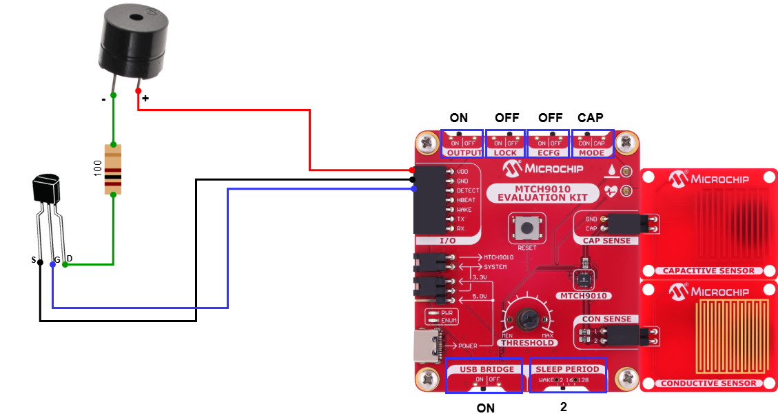
Theory of OperationThis application detects the presence of liquid using the capacitive or conductive capabilities of the MTCH9010 device. When water is detected on the sensor surface, the MTCH9010 triggers an active buzzer to provide an audible alarm. The buzzer remains active and continues to sound as long as liquid is detected. Once the liquid is no longer detected by the sensor, the buzzer automatically turns off.
The positive pole of the active buzzer is connected to the VDD pin of the MTCH9010 Evaluation Kit, while the negative pole is connected to the Drain terminal of an N-channel MOSFET transistor. The MOSFET transistor is used in a common-source configuration to amplify the current required by the buzzer. The Source terminal is connected to the GND pin, and the Gate terminal is connected to the DETECT pin.
An active buzzer produces a single, predefined tone, generated by an internal oscillator. To control the sound intensity, a 100Ω resistor is introduced between the negative pole of the buzzer and the Drain terminal of the transistor. The resistor can be adjusted to meet specific needs. By using the resistor, the current flowing through the buzzer is adjusted, which affects the loudness of the buzzer without altering the frequency of the sound wave.
The buzzer is controlled by the DETECT pin of the MTCH9010. When the pin is set to High state, the buzzer is activated and produces sound. When the pin is set back to Low state, the buzzer is deactivated and remains silent. If any liquid is detected, the DETECT signal will remain in a High state until the sleep period expires and a new measurement is made. If the next measurement determines that liquid is present, the DETECT signal will remain High. Otherwise, it will go Low. Below is an example of five consecutive measurements, out of which the first two show that liquid was detected. The measurements are separated by the sleep period.
In this example, the MTCH9010 is configured using the on-board slider switches. This mode provides a simple, hardware-based setup method without requiring a computer or serial terminal connection. The following configuration is made on the device:
- OUTPUT: configured to ON
- LOCK: configured to OFF
- ECFG: configured to OFF
- MODE: configured to CAP
- USB BRIDGE: configured to ON
- SLEEP PERIOD: configured to 2 seconds
The threshold can be manually adjusted using the tuning knob.
The Extended Output mode via UART is enabled through the OUTPUT switch configured to ON. By default, both the raw measurement and delta parameters are provided. The GPIO configuration used in this application is determined by the LOCK and ECFG sliders. LOCK configured to OFF means that the system does not use the parameters stored in the Nonvolatile Memory (NVM), and the ECFG configured to OFF disables the Enhanced Configuration mode in which the user can set the desired parameter through serial communication. The MODE switch determines which detection method is used; for this example, the capacitive method was chosen. The interval at which measurements are made can be adjusted using the SLEEP PERIOD slide. For this application, the sleep period is configured to 2 seconds. To enable communication between the computer’s USB port and the UART interface on the MTCH9010 Evaluation Kit, the USB BRIDGE switch is placed in the ON position.
Slide switch changes that configure the MTCH9010 take effect on power-up or after pressing the RESET button.
ResultsThe MTCH9010 supports UART output. The parameters can be visualized using a serial terminal connection. The serial communication parameters are as follows:
- Baud rate of 38400 bits/second
- Eight data bits
- No parity bit
- One stop bit
Below is an example using the MPLAB® Data Visualizer terminal.
The figure below shows the analog drive signal for the buzzer. When the buzzer is triggered, the signal transitions from a steady state to a repeating waveform pattern. This pattern represents the electrical pulses sent to the buzzer, causing it to produce sound.


Comments