The birth of this project is strictly related to the development of my ARKeytar MIDI controller. After I built the ARKeytar, I realized that I wanted to expand its capabilities in terms of musical expression. Also, I needed to route the generated MIDI messages towards my keyboard synth, or towards my PC, through a MIDI interface, to control VST synths.
In order to change the MIDI routing while letting my whole setup connected, I decided to build a MIDI merger with the capability of managing also an expression pedal and a switch pedal.
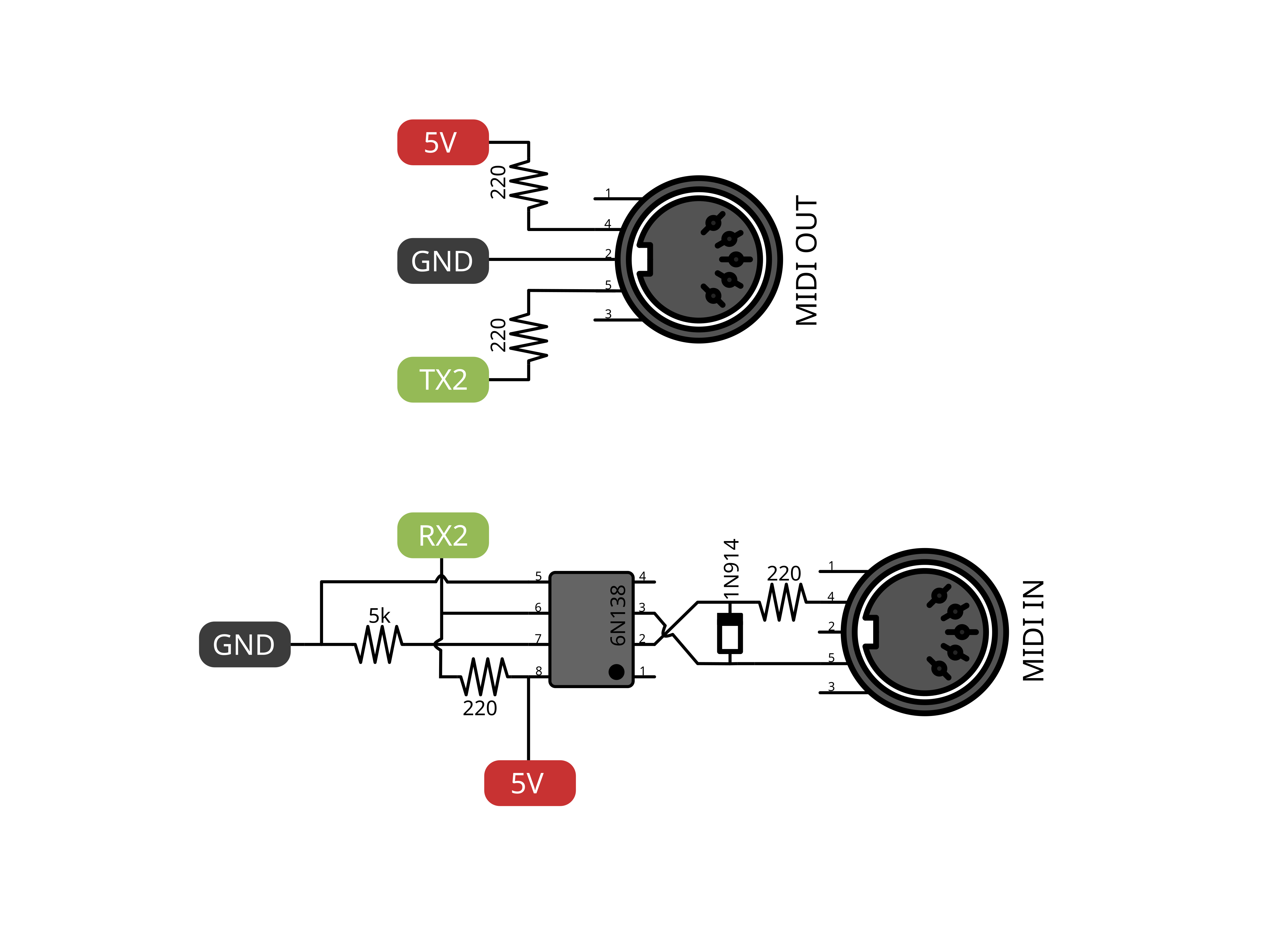
Given the need of managing two serial ports (two MIDI inputs, and two MIDI outputs), the Arduino Mega board was chosen since, unlike the Arduino Uno, it is able to manage more than one serial port.
The idea is to keep the ARKeytar MIDI controller and my keyboard synth connected to the MIDI input of the merger, while the two MIDI outputs are directed towards the keyboard synth and the audio-MIDI interface. By means of two SPDT (single-pole double-throw) switches with three positions, one can tell the Arduino the destination MIDI output port for each of the two MIDI inputs.
The MIDI input 1 can be sent to one of the MIDI outputs or to both of them, while the MIDI input 2 can be sent to one of the MIDI outputs or to none of them. The routing of MIDI input 2 includes the possibility not to forward the generated messages, since the connected keyboard can be used to control only its internal sounds, instead of controlling some VST software. Now, by simply moving two switches, I can configure the routing of my MIDI devices.
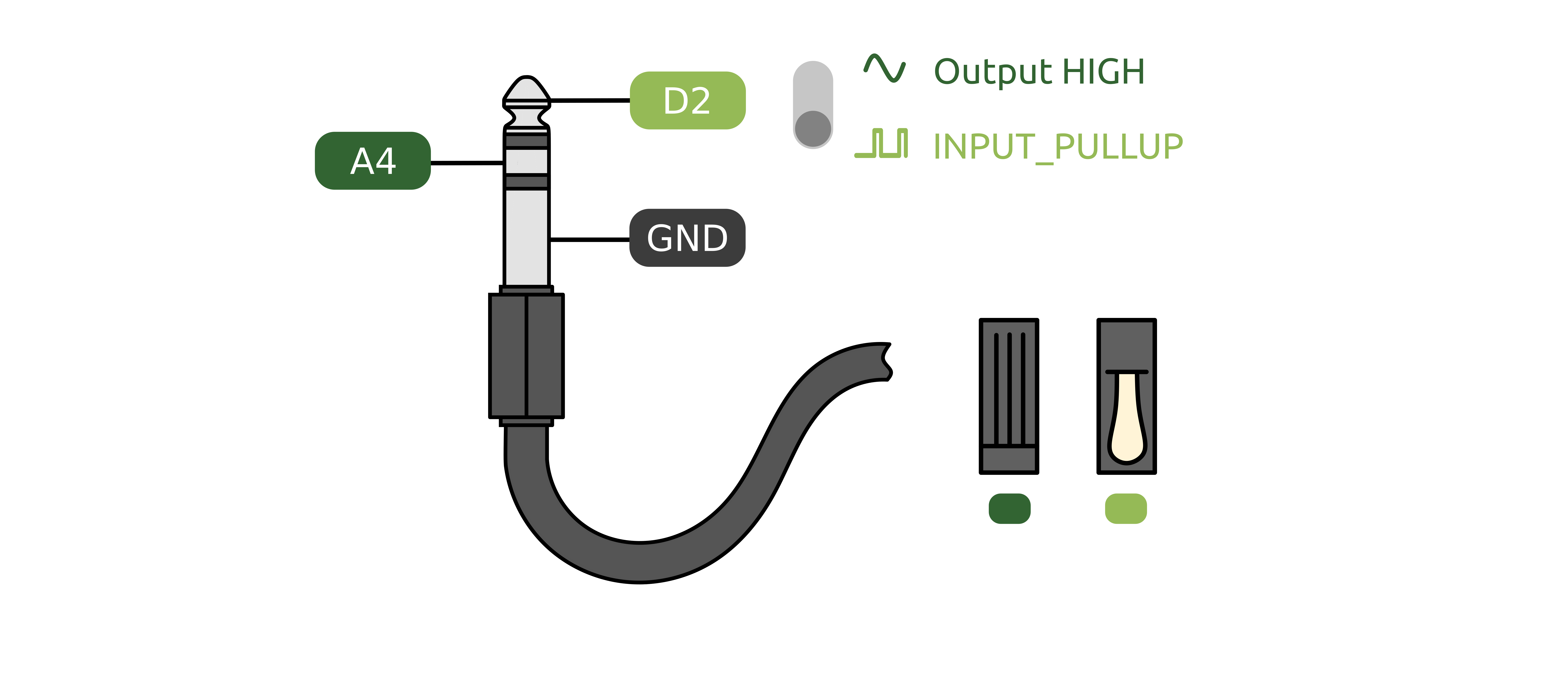
The rear panel of the merger presents also two jack ports. One of them can be used to connect a switch pedal. The other one can handle both an expression pedal or a switch pedal. The behaviour can be selected with a switch on the top panel which changes the configuration of the Arduino pins to which the pedal is connected.
The digital pin D2 is set to INPUT_PULLUP when using the pedal as a simple switch. Otherwise, it is set as an output with state HIGH. In this case, the voltage value of the central pin of the stereo jack socket is read with analogRead() on the analog pin A4. The remaining pin is always connected to GND.
Once the pedals states are read, MIDI messages are generated if changes happened. The control change destination can be programmed, and the destination MIDI output port can be selected, for each pedal, using switches on the top panel. The Arduino merges the routed incoming messages together with the ones generated following to the pedals action.
An additional switch is present to add some generic setting that can be assigned by editing the code in Arduino IDE. For the same reason, a digital encoder is present. Moreover, additional MIDI messages, like program change messages can be generated with three stomp switches.
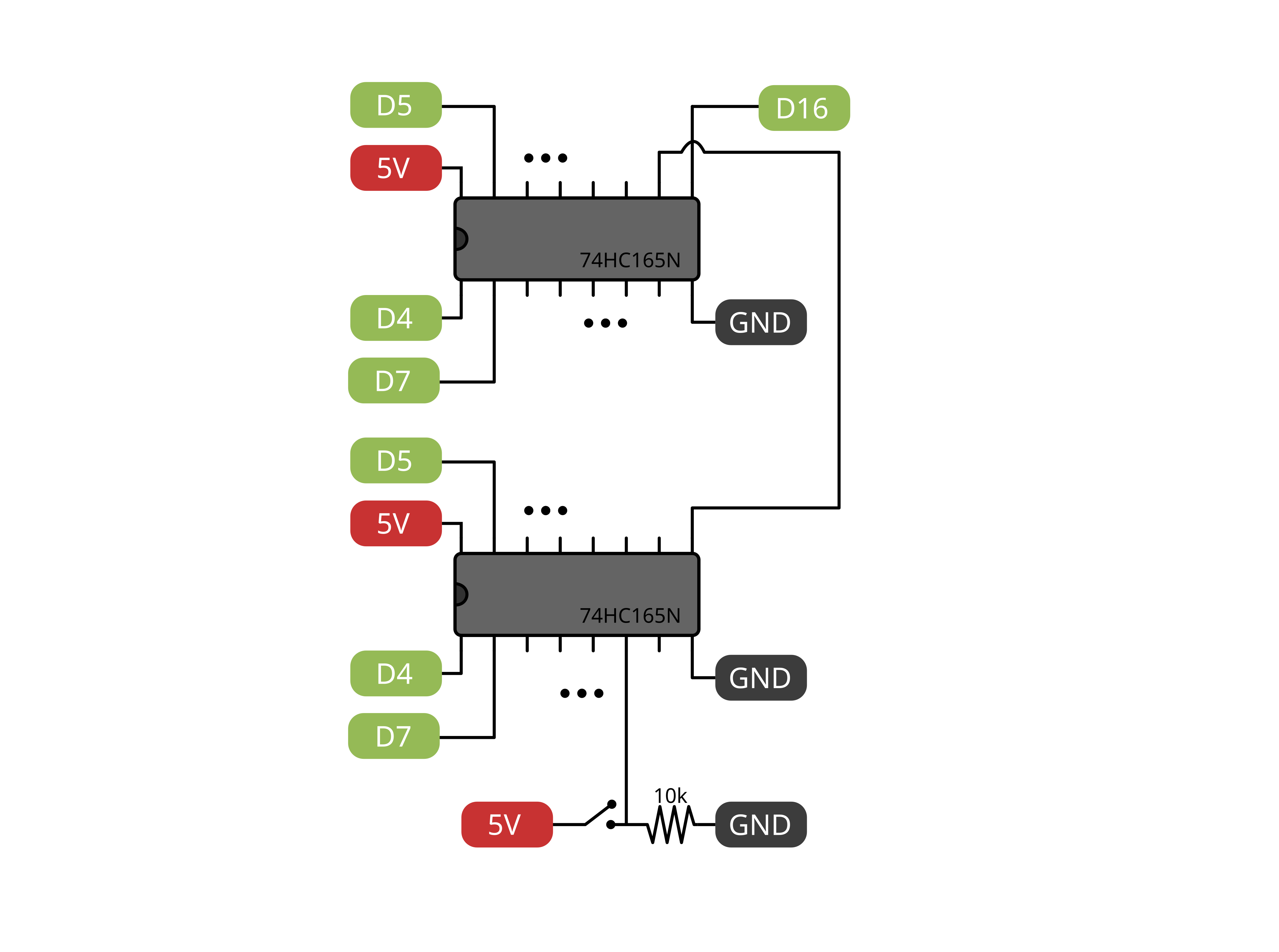
All the switches are connected to the Arduino using a pair of shift registers. This was useful mainly to simplify the connection between the front panel and the Arduino Mega, which is screwed to the base. A reduced number of channels was used in this way.
The merger also presents three LEDs for analyzing the type of the incoming MIDI messages. The green and red leds are activated by note on and note off messages respectively, while the blue led is triggered by pitch bend messages, which are the majority of the MIDI messages sent by the ARKeytar, and by control change messages.
I chose a solid aluminum box as the enclosure for the project. The base dimensions are 189 mm x 121 mm. The thickness of the box, excluding the later additions is 38 mm. Six holes were drilled for the SPDT switches, three for the stop pedals, three for the LEDs, and one for the encoder.
At the beginning, I did not drill the MIDI ports holes since I needed a good alignment with the four MIDI sockets, soldered to the internal circuit.
The procedure I followed was:
- Soldering all the main circuit, MIDI ports included, to a prototype PCB board. In order to accommodate the Mega inside the merger enclosure with a rigid connection, and without soldering, male pin headers were used. The space between the Mega and the PCB could be used to fit circuits and cables. Room was left also for possible future expansions of the project. MIDI circuits were soldered on the base, together with the sockets, and were connected, to the Arduino serial ports.
- Screwing the PCB to the aluminum case base
- Opening the four MIDI ports, and Arduino USB holes. For the MIDI ports a 16 mm diameter mill was used instead of a drill bit, since the case wall was slightly oblique while the MIDI sockets were not.
- Drilling all the required holes to fit switches, LEDs and encoder. Besides the three LEDs for analyzing the MIDI input, a led was added to indicate that the merger is connected to the power supply and is turned on.
Since all the switches needed the 5V connection, and another 1 or 2 connections with digital pins, I tried to limit the number of cables connecting the case base and the top panel. Two shift registers were placed under the top panel, so at least the cable mess was limited to the top panel. This helped in keeping some tidiness in the merger base. A ribbon cable was used to connect the front panel and the base.
I included the encoder and the stomp pedals since I plan to give them a function like changing settings from a list and sending program change messages. However, they are not active at the moment.
All switches but two, are connected to two digital pins. The switches can be in three positions so that they can deliver the 5V to one of the pins or to none of them when they are in the central position. In this position, both the digital reads are LOW. If one of them is HIGH, the corresponding setting is selected. They can never be in HIGH state at the same time, due to the design of the connections. In this way three possible states are possible.
In particular:
- Switch number 1 routes the MIDI input 1 to output 1, to output 2, or to both.
- Switch 2 routes the MIDI input 2 to output 1, to output 2, or to none.
- Switch 3 selects the digital or analog behaviour of pedal 2. Pedal 1 acts always as a switch
- Switch 4 routes the MIDI messages generated with pedal 1 to MIDI output 1 or 2, or to both.
- Switch 5 routes the MIDI messages generated with pedal 2 to MIDI output 1 or 2, or to both.
- Switch 6 is not currently assigned to any function.
The stomps, instead, can be in two positions only, and are connected to a single digital pin. If a single message needs to be sent at the time of a pressure, the change of state is used to trigger a single message. Otherwise, the state can be used to determine which message should be sent among a set of two messages, like an on/off button.
- The three stomps and the encoder (with its button) are not currently assigned to any function.


_wzec989qrF.jpg?auto=compress%2Cformat&w=48&h=48&fit=fill&bg=ffffff)


Comments