

Hardware components | ||||||
 |
| × | 1 | |||
| × | 7 | ||||
| × | 6 | ||||
| × | 2 | ||||
| × | 8 | ||||
| × | 2 | ||||
| × | 1 | ||||
| × | 5 | ||||
| × | 5 | ||||
| × | 5 | ||||
| × | 2 | ||||
| × | 1 | ||||
| × | 12 | ||||
| × | 1 | ||||
Software apps and online services | ||||||
 |
| |||||
 |
| |||||
| ||||||
| ||||||
 |
| |||||
| ||||||
Project Level : Intermediate to Advanced
Software Prerequisites
- Windows 10
- Visual Studio 2015
- Android Studio
- MPLAB X IDE (with XC8 Compiler)
Introduction
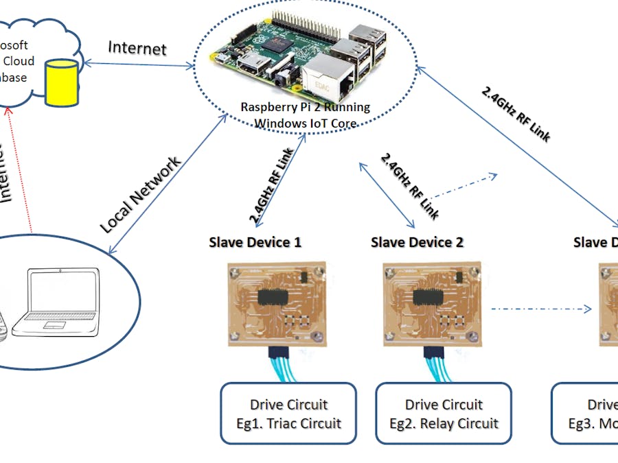
Windows IoT The new Windows IoT enables a handful of features for developers to create powerful and efficient applications in lesser time. A Windows IoT powered Raspberry Pi is the key element of this Home Automation project.
The Raspberry Pi acts as master of the system. The Raspberry Pi connects to a number of slave devices through 2.4GHz ISM Band RF Link. Slave device is a PIC18F microcontroller based board having necessary circuitry and program for establishing a duplex wireless link with Raspberry Pi. Every slave device has same circuit and PCB design except distinct Device ID/Address(should be unique) and Device Type number. The C# program on Windows IoT is able to handle any number of slave devices simultaneously.
Features
1. Smartphone/Computer can be used to control Home Appliances.
2. The Raspberry Pi connects to one or more Slave Device(s) through ISM band 2.4GHz wireless link.
3. These slave devices allow Raspberry Pi to control Home Appliances/Electrical Devices remotely.
4. Different Levels of controlling is possible.
a. Relay based controlling (Simple ON/OFF function).
b. Triac Based Controlling (Light intensity or average power can be controlled)
c. Motor Control (Either Triac based or DC Motor Driving)
d. User can add other control methods like PWM, Feedback Systems etc. without much effort.
5. I have programmed a mobile application to enable both Internet and Local network (Datagram Socket) based controlling.
6. There is no need to change Raspberry Pi's program for adding new slave devices. Just hit 'add me' button of the slaves. Raspberry Pi will automatically add the device to the network (Auto Scan option is also available).
7. Both digital and analog sensors can be connected to a slave device. Since the Raspberry Pi Slave Device communication is bidirectional RF link, Raspberry Pi reads the sensor readings without any physical connections.
8. A neat GUI C# program will help users check connection status, network monitoring, device control and more.
9. A timer based control option is present. Set the time when you want to off/on a particular device, Raspberry Pi will do the rest.
10. It is easy to introduce Speech Detection/Voice Commands without modifying much.
11. Sensor readings can be written to Azure Database with time stamps. Electrical Devices can also be controlled thgrough Azure Cloud Database.
Raspberry Pi Connections
In this home automation system Raspberry Pi is free from any physical connections other than nRF SPI Communication link [excluding essential connections like Power, Ethernet/WiFi and HDMI(Optional)]. All the controlling, Monitoring, Decision making, Triggering and switching operations are done in Raspberry Pi. Raspberry Pi uses a duplex wireless link (Not WiFi or Bluetooth standard) to communicate with slave devices. The whole C# program can be download from the software section of this article(GitHub).
(Note: Compiling to x64/x86 platform may not work properly due to hardware IO requirements of the program.
Note: The nRF class I wrote for the wireless module didn't utilize the true potential of that module. I will update the GitHub nRF class file once I get enough time.)
The C# application enables 3 ways to control home appliances or even industrial systems.
1. The RPi's GUI. A good looking C# GUI running inside Raspberry Pi will allow you to monitor network commands, different sensor readings, control home appliances, and automatic controlling along with other background tasks like Azure DB read/write, timers, etc.
The device box lists all available slave devices. You can remove or add slave devices at any time.
At the top of the GUI you can see different sensor readings extracted from slave devices through nRF wireless link. The C# application uses these sensor readings for automatic controlling of electrical devices.
At the bottom, the 'network log' box shows all commands received from Mobile/Computers through Azure Cloud Database or LAN with connected device's IP address and name. Below that, a status bar is placed. Which shows all necessary information and notifications to the user. By switching on "Auto Update" button, you will get live updates from selected slave device's sensor data (It is possible to write these sensor data in Azure DB with time stamps) . This button can also be used to check whether the slave device is within the wireless range of nRF24's RF link or not. The 'Autocontrol' checkbox is to enable "Auto control" mode, which can adjust light intensity based on the light intensity sensor readings. It is also possible to make alarms on human presence with the help of the PIR sensor.
Along with controlling it is also possible to transfer messages either through LAN or Azure Cloud DB.
2. Local datagram packets.
I have developed a simple Android and Windows Universal application for controlling devices through the local network (LAN).
3. Azure Cloud Database based controlling.
Above said same application has a special mode to send commands to Raspberry Pi through the Internet (via Azure Cloud)
(Note: I made these apps just to test the functionality only. If you are good at GUI designing, you could make it better
Note: It is not possible to use this app without a powered Raspberry Pi running Windows IoT and the above said C# app.
Note: All network commands start with a character '!' you can see the whole commands in the MainPage.cs file of Pi's C# program.)
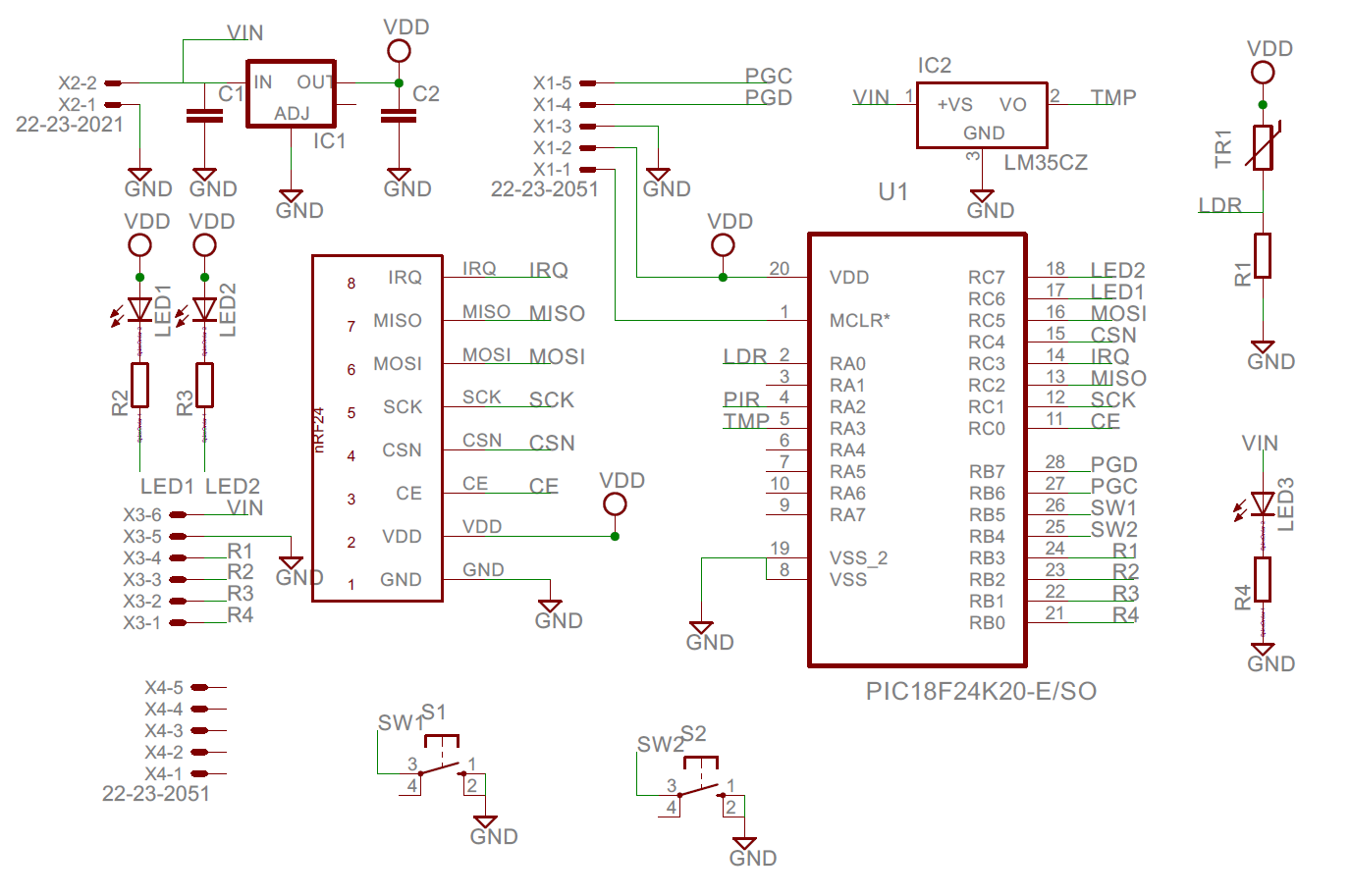
Slave Device
Slave Device is a PIC18F24K20 based board with nRF24 wireless module. All slave devices have same Circuit and Firmware program, except a separate device type code and unique ID/Address number. So, it will be easy to make any number of slave devices without much effort.
Every slave device has one "AddMe" and "RemoveMe" buttons for registering that slave to Raspberry Pi or Removing the slave.
Update (15/09/2015)
I have added an "Auto Scan" option. Now, along with "AddMe" button you can scan for slave devices within its wireless range. This option will allow you to add all slave devices within the wireless range of Raspberry Pi without pressing "AddMe" button of slaves. All you need is just "Scan" and wait for available devices to list.>
Sensors Available
1. Temperature sensor (LM35)
2. Light intensity sensor (LDR)
3. PIR Sensor (HC-SR601)
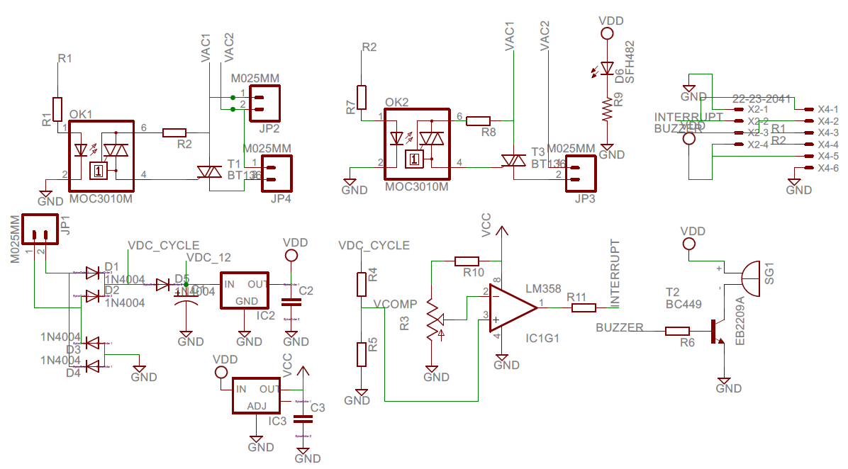
Slave Device Schematics and PCB Design
You can download Eagle CAD files from the Hardware section of this article.
(i didn't find any good nRF Eagle Library on internet. So I made my own. You can find this nRF24L01+ library at CUSTOM PARTS AND ENCLOSURES section of this article)
How Does Slave Device Work
Slave Devices are similar to expanding IO ports of Raspberry Pi wirelessly. Even though wireless communication system is a bit complex, it is very convenient to use it. It will never be possible to wire your entire home just to implement Automation system. So, I decided to go for wireless system. Another added advantage is that, you can expand your Home Automation System anytime to any room without adding or updating a single line of code. All you need is 'Hit the AddMe' button of slaves. Imagine doing the same with a wired system !!.
As I said, slave device expands the range of Raspberry Pi with flexibility and more controls. It is up to the user to decide which control function he/she should assign to a slave device. Just like templates, I have made 5 different types of slave controls. You could easily expand it to any number any type without much effort.
public enum device_type : byte
{
Test_Device = 0, //Used a prototype for testing
Triac_Device = 1, //Triac/Solid state relay high speed switching
Relay_Device = 2, //Common Relay Control
Buzzer_Device = 3, //Buzzer and Alarm Control board (Not implemented)
Motor_Device = 4
};
The above enum statement shows possible slave types in my program.
A. Triac Device
(Note: You can omit this type of Slave Devices if you are not familiar with power devices.)
Triac is an AC power device which can be used in fast switching applications like speed control of motors, light intensity controlling, etc. Appropriate triggering is necessary and commutation methods should also be considered while designing a Triac Circuit. Integration of the slave device and triac control board made the system even more useful and flexible. Triggering of Triac is a bit tricky. You need a zero crossing detector to know zero crossing points of Alternating Current (LM358). The PIC18F24K20 microcontroller inside the slave will identify zero crossing points (From Square wave out of LM358) and trigger the triac based on triggering delay that we have sent from the Raspberry Pi.
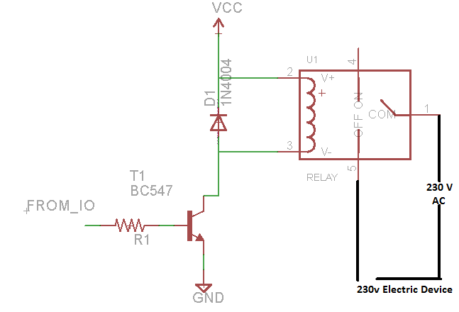
B. Relay Device
It is very easy to configure and connect Slave as a Relay Device. You don't need any extra large circuitry other than a 5v or 12v relay, BC547 NPN transistor 1k resistor and 1N4001/1N4004/1N4007 Diode or ULN2003 Darlington pair IC . I recommend using ready to use simple relay boards (It is very cheap and easy to get, won't cost you more than 2USD[At least in our area])
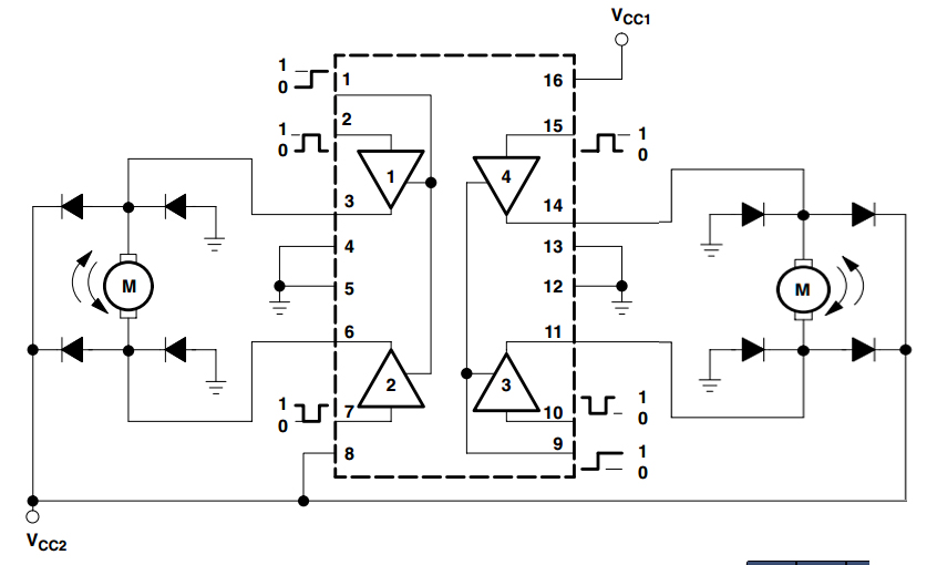
C. 12v DC motor Device
It is an extension of relay device. Here instead of relay circuit, the slave device controls two 12v DC motors. The popular motor driver IC L293 or L93D can be used in these devices.
Raspberry Pi Slave Wireless Communication
For the wireless communication between Raspberry Pi and Slave Devices, I used nRF24L01+ modules and created a custom packet structure inside payload of 10 bytes.
Packet Type and Slave Device ID
An "add_me_packet" from slave device will register that slave device ID in the Raspberry Pi's Device List. The Raspberry Pi will use this unique device ID for further communication with that particular Slave Device.
Similarly, data packet is usually issued by Raspberry Pi for control operations.
A slave device after receiving Update packet request from Raspberry Pi will respond with its sensor readings and connected Devices' state as a data packet to the Raspberry Pi. You could easily change my 10 Bytes packet system to 20 or 32(Max) packet system, if you know how the system works.
Device Type
We have seen Triac Device, Relay and Motor Control Boards. How Raspberry Pi knows or identifies the type of operation the slave is going to perform (You have already know, every slave device has same firmware and circuit). This is defined by 3rd byte of the packet.
To configure a Slave Device as Motor Device you need to change #define statement of the given embedded C program.
//#define triac
#define relay //////need to change according to your device
#define device_id 59 //////need to change according to your device
///////////////////////////////////////////////////////////
#define device_type 4
///Device type declaration for program
/*
Test_Device = 0,
Triac_Device = 1,
Relay_Device = 2,
Buzzer_Device = 3,
Motor_Device = 4
*/
For Triac Device
#define triac ///Uncomment this define statement
//#define relay //////need to change according to your device
#define device_id 59 //////need to change according to your device
///////////////////////////////////////////////////////////
#define device_type 1 ///change to 1
For Relay Device
//#define triac
#define relay //////need to change according to your device
#define device_id 59 //////need to change according to your device
///////////////////////////////////////////////////////////
#define device_type 2
Some Communication Situations
---------------------------------------------------
Other Useful Links and Notes
- For enabling controlling over internet, you need to register for Azure Account and use Azure Database. This link will give you a brief intro about Azure DB and Azure Mobile Services Azure
- (Pi's C# uses 1st table entry only)
- It is possible to insert different sensor readings into Azure Database. I didn't use this in my system, but you need only 2 lines of code to do that. Just place update code the
azureMonitor_ticktimer tick event.
//Note free Azure Subscription has 20MB database size limit.
- You have to enter your own Azure subscription key, table entry ID, and other information in order to work the my program on your computer/raspberry pi/mobile phone.
public static MobileServiceClient MobileService = new MobileServiceClient(
"https://myandroid.azure-mobile.net/",
"Replace this string");
and
item_default.Id = "xxxxxxxxxxxxxxxxxxxxxxxxxx";
- If you are not good at PCB making and Circuit designing, I recommend Arduino or other ready to use boards. For a smaller form factor and low cost go for custom designs.
//Inside this case statement of data_received(byte[] data_byte) function
case (byte)packet_type.update_packet:
..................
if ((bool)autocontrol.IsChecked)
{
byte[] bb = {0x00,0x00, 0x00
, 0x00 , 0x00 , 0x00 };
if (temp < 140)
bb[0] = (byte)(temp);
else
bb[0] = 140;
bb[1] = data_byte[8]; //Added code (This will enable buzzer based
//PIR reading.
bb[2] = lastitem.device3_state;
bb[3] = lastitem.device4_state;
nrf_send_data(bb, lastitem.device_address, packet_type.data_packet);
}
.......
}
One last note
Windows IoT Home Automation vs Other systems
Appendix
Some of you may not be familiar with microcontrollers (uC) and uC programming. I will explain some essential things you needed to burn Slave Device's .hex file.
1. You need to install Microchip's MPLAB X IDE and XC8 Compiler in order to recompile the program. You don't need to install XC8 compiler if burning the program is the only requirement.
You can download MPLAB X and XC8 compiler from this link MPLAB X and XC8
2. A programming hardware tool or simply programmer is essential to burn the program into uC. For Microchip's PIC controllers PicKit3, PicKit2 or ICD3/2 can be used. (MCLR, VDD, GND, PGD and PGC pins need to be connected).
3. You can see the header for PicKit3 in the PCB design.
How to install Windows IoT on Raspberry Pi
.........................................................................................................................
It is not possible to explain the whole program here. So, please read comments of the given code files. I have added some useful code snips at the end this article.
Feel free to post your comments, opinion and doubts regarding this project.
Thank you :)
Anand.


Comments