
Hardware components | ||||||
 |
| × | 1 | |||
| × | 1 | ||||
| × | 1 | ||||
| × | 1 | ||||
| × | 1 | ||||
| × | 1 | ||||
| × | 1 | ||||
| × | 1 | ||||
| × | 5 | ||||
| × | 1 | ||||
_ztBMuBhMHo.jpg?auto=compress%2Cformat&w=48&h=48&fit=fill&bg=ffffff) |
| × | 1 | |||
Software apps and online services | ||||||
 |
| |||||
Hand tools and fabrication machines | ||||||
| ||||||
 |
| |||||
Behavioural testing of rodents is a key class of experiments in clinical research, providing a tool for the testing and development of treatments to help patients in need. However, commercially available equipment is often prohibitively expensive, limiting the number of labs with access to these tools. In our project we set out to design, construct, and validate a low-cost behavioural chamber capable of evaluating forelimb performance in rats in an automated fashion - a common task in neuroscience research [1-2]. Our team has successfully constructed an acrylic cage specifically designed for this purpose, equipped it with the sensors necessary to automate the behavioural task, and developed and validated the code to operate it using an Arduino board. The chamber was additionally designed to be easily modifiable, able to be extended to many other rodent behavioural tests. We have also developed an automatic pellet dispenser, a key component in automated behavioural research, which can be coupled with our or other behaviour box.
Task principleThe task which the rat carries out in our chamber is known as the Wishaw test [3], which tests the animal's coordination and grip strength by testing its ability to grasp a sugar pellet with its forelimb. Our behavioural chamber is primarily composed of transparent acrylic, inside which a rat is placed. This chamber is designed with a hole on one of its walls, allowing the animal to reach out with its paw to grasp a sugar pellet placed on a holder on the other side. Each experimental trial is triggered by a laser tripwire (laser pointer + photodiode), which the rat crosses to reach the opening in the chamber. The interruption of this signal triggers, through an Arduino board, the flashing of an LED with which video recordings from a GoPro Hero7 camera can be synced with other equipment connected to the chamber/animal (electrophysiology, strength meter, touchscreen, etc.). This camera is used specifically for its ability to acquire video at 1080p at 240fps– a higher framerate than most cameras utilised in behavioural kinematic analysis – at a commercially competitive price.
To reset the task (i.e. receive a new pellet to grasp), the rat will be trained during its habituation period (a standard period of time in behavioural research where the animal is taught how to use the equipment to acquire sugar pellets as a reward) to walk out of the section of the chamber where the slit is placed. In doing so it will hit another tripwire (photodiode + laser pointer pair), causing the dispensing of a new pellet. This is triggered by the Arduino board, which moves a stepper motor of the pellet-feeder system to deploy a single new pellet.
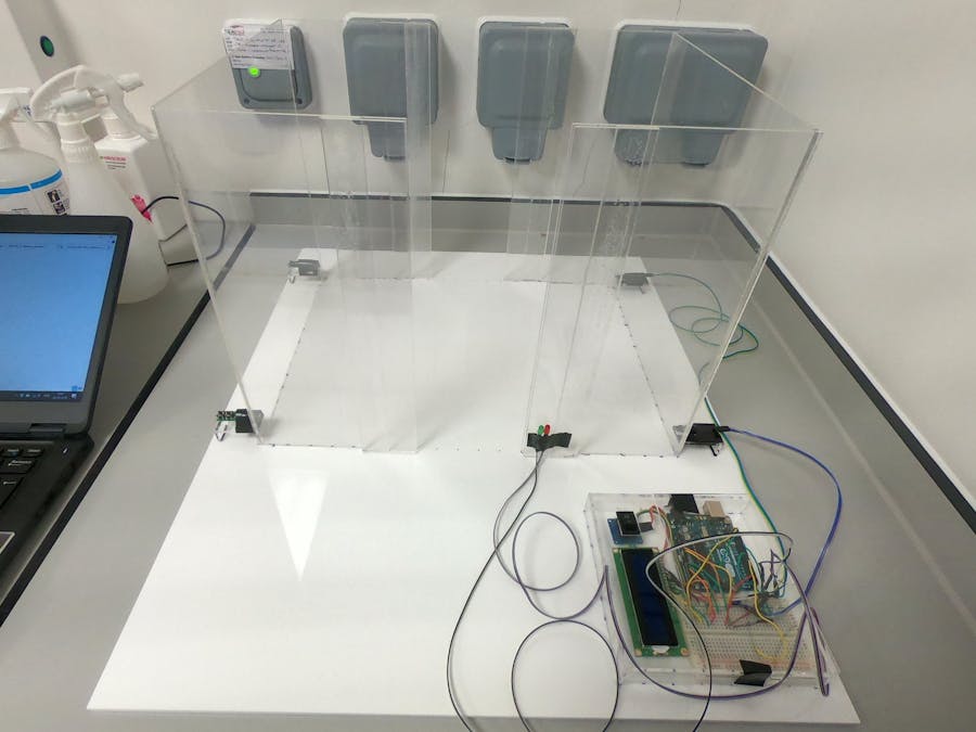
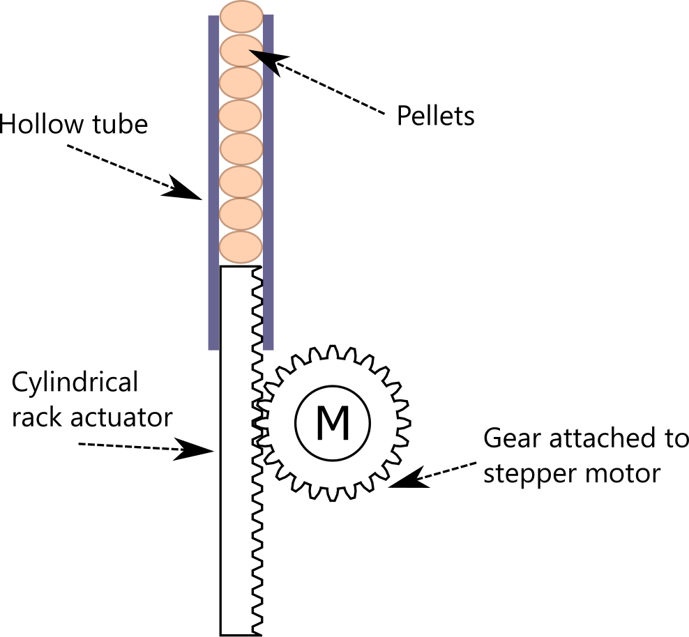
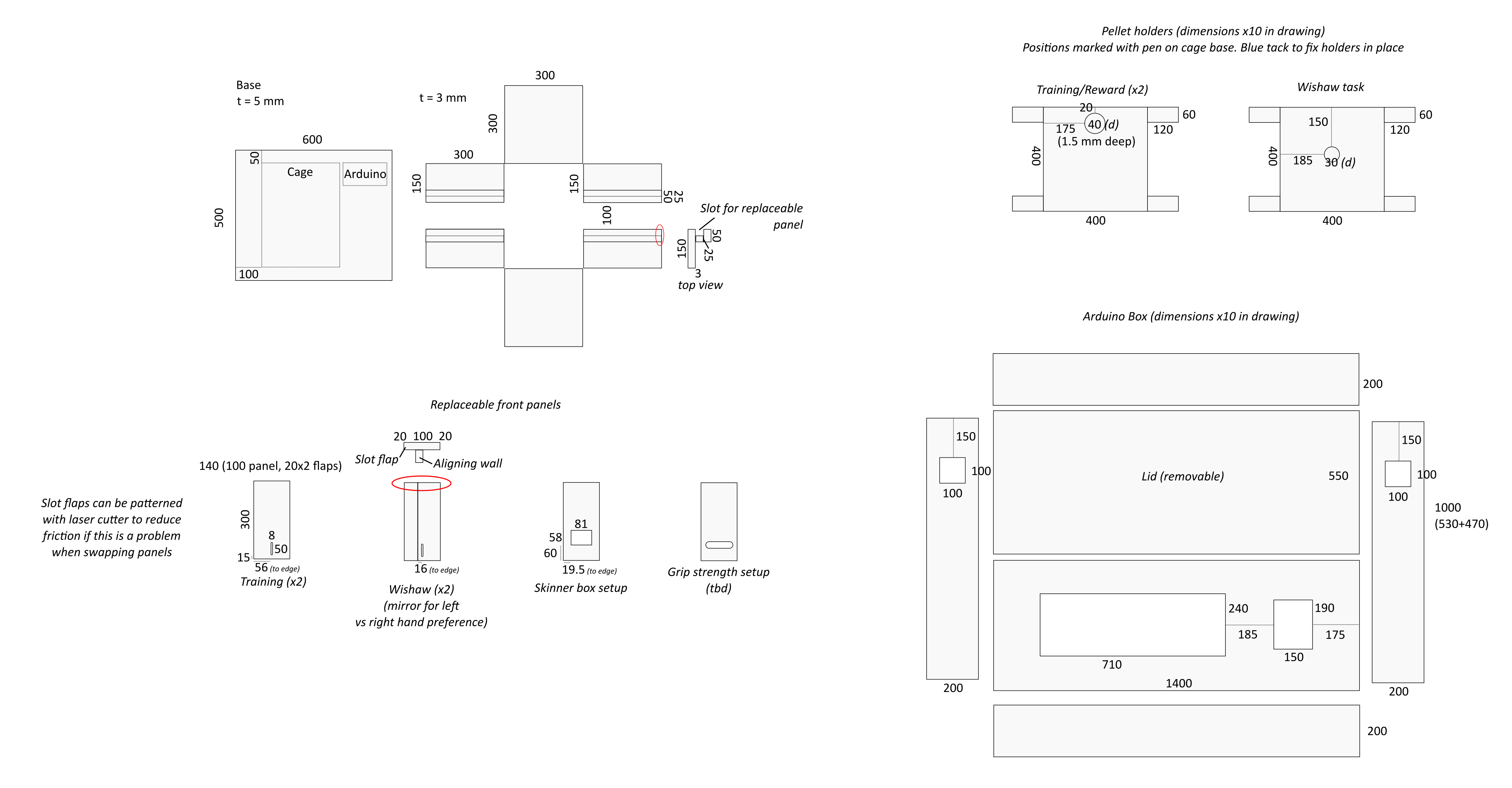
This task will be repeated without need for input from the experimenter for a pre-defined number of trials. The number of times the rat has carried out this task will be displayed in an LCD screen on the side of the chamber. A button is also available for the experimenter to reset the chamber when necessary, and is kept informed as to the current task number through an lcd screen run by the Arduino. The operation is summarised in Figure 1. The layout of the chamber and dimensions for the acrylic sheets are given in Figure 2. Figure 3 provides pictures of the box. Figure 4 provides a diagram of the pellet dispenser, while a video of the fabricated version in operation is given in Figure 5 (CAD designs of the various parts of the dispenser are found in additional attachments).
Our group worked through multiple iterations of acrylic box designs to develop one best suited for our purposes. We specifically focused on designing a cage which could easily be used for more than one behavioural test, not just the grasping Wishaw test. The final version of our behavioural box features removable front and back panels, which provides the task. Aside from panels with a slit through which rats can grasp pellets (i.e. panels for the Wishaw task), we have also built a panel with a touchscreen (designed to be a Skinner box task) and a panel with a grip strength meter (testing rat grip strength). The rest of the components (laser tripwires, camera, pellet dispenser, etc.) are present in all versions of the box, allowing a multitude of different behavioural tasks to be carried out in the same automated, kinematic analysis-enabled setup. A video of a rat making use of the box as part of the Wishaw test is presented in Figure 6.
We also developed Arduino code to operated the cage in an automated fashion. As described above, this involves the use of laser tripwires which the animal walks through during normal chamber operation in order to deliver new pellets. The code also allows for voltage pulses to be sent out to other hardware setups, which allows syncing of external hardware components (for example, grip strength testers, electrophysiology hardware, etc.) with video recordings of animal behaviour. This, combined with the ability to swap over panels to change the behaviour being evaluated, greatly enhances the number of tasks and applications for which our behaviour box can be used for.
Our behavioural chamber consisted of four key components: a chamber to house the rat, a feeder to dispense pellets for the rat to grab (the task itself), a camera setup to record the grabbing motion, and an emitter-sensor system to automate the procedure. At the time of writing, we have built and validated the chamber, pellet dispenser, and emitter-sensor system; and are currently developing the camera setup. Throughout the course of the project, we had to adapt our original design and introduce multiple changes, illustrated in Figures 6 and 7.
Our initial chamber consisted of a box with an opening on one of its sides to allow the rat to reach out and grab the pellet. However, we found that animals tended to approach such slits from different angles, resulting in inconsistent reaching out and grabbing motions. As this variability would have difficulted analysis of the task, we soon modified our cage design to incorporate a short tunnel leading to the aperture. This served to “align” the rat and improve the consistency of the task.
The emitter-sensor system consisted of two pairs of infrared LEDs (emitters) and infrared sensors. These proved to be ineffective for our setup, as LEDs tended to be too weak to provide reliable intensity readings, and the infrared wavelength made them very difficult to align with the sensors. We therefore substituted the infrared LEDs for commercial (red) laser pointers, which provided much more reliable results and were easier to align. Additionally, with the introduction of the small tunnel to the behavioural box, we were able to simplify the system to consist of a single emitter-sensor pair(the resetting of the task being done by the rat having to leave the tunnel, rather than the triggering of the back sensor). We also built into the system a display to inform the user of the number of reaches the rat had performed, and a switch to reset the chamber when necessary; and developed the code to operate these via an Arduino board.
Our initial design for the pellet dispenser consisted of a large pellet box, from which single pellets were pushed down one at a time. However, the collapse of a pile of spheres (pellets) into a single file was determined to be prone failure, with pellets clumping above the exit tubing. We therefore switched to a dispenser system where pellets where pre-loaded into a tube. We also designed and fabricated a system to both push pellets out and dispose of them after a predetermined amount of time if the animal failed to grab them, using a single stepper motor.
Finally, we have also bought a small-size camera capable of high-speed recordings to record the grabbing motions of the rat, and are currently adapting code to control it wirelessly via an Arduino board(therefore syncing it with the emitter-sensor system).
Update (26/07/2019)
We have carried out initial tests with rats in our chamber. Our current design allows rats to freely move and successfully guide them towards the task window (Figure 8). In the coming weeks we will train rats to seek sugar pellets, which will allow us to validate our task.
Most rodent behavior systems consist of a several common components:a housing chamber, a reward system (e.g. dispenser for sugar pellets), a task for the animal to carry out, and a camera to record the task. Although our chamber was initially designed for a forelimb grasping task, most of its components are suitable for many other tasks. We therefore seek to expand our behavioural chamber to include other behavioural tasks common in rodent behavior research. We envision our chamber becoming a “plug-and-play” type of system, where with minimal changes to the chamber an experimenter will be able to perform a large variety of tasks to evaluate different animal behaviours.
The following additions will be carried out: development of new rodent tasks (installation of hardware and modification of Arduino code to operate it), and development of a user interface and guide to allow the experimenter to choose and prepare their task of choice. The tasks will consist of a grip bar and force meter(evaluation of limb strength and coordination), a touchscreen (Skinner box setup, testing learning and memory), and a pressure mat (testing gait and movement). The equipment for these tasks will make up the bulk of the follow-on funds (together with the animals used to validate these tasks), with th eremainder being used to modify our current cage where necessary. Our current Arduino code will be modified to operate the cage with each of these tasks, though these changes will likely be minor. Finally, a user interface will be developed to guide the experimenter when choosing a specific task, and helping them set up the chamber appropriately. This will be operated by the user via the 4D Systems touchscreen provided with the Biomaker Arduino package.
As we have moved quicker than expected in our project, we anticipate that we will be able to implement these additions by the November deadline. Our current timeline is to finish integrating the camera setup into our current forelimb-grasp system and begin our first validation tests with rats by mid-August. While one of our team members will work on processing of the video recording data, the rest of our team will have time to develop these additions throughout the remainder of the summer.
Items for additional chamber tasksForce gauge (evaluation of limb strength and coordination):
RS PRO Force Gauge RS232, USB
Part no: 111-3689
Price: £390.00
Pressure mat (testing of gait and movement):
7.0" SMART HMI Display Resistive touchscreen
Part no: GEN4-ULCD-70DT
Price £120.00
Skinner box touchscreen (testing of learning and memory):
4.3" SMART HMI Display capacitive touchscreen
Part no: GEN4-ULCD-43DCT-CLB
Price: £95.00
TimelineBelow is a description of the project timeline we are following.
June: Acquire materials, develop code to operate cage.
July: Build prototype cage, build prototype feeder.
August: Validation in rats, modification of cage design based on experience with rats.
September: Development of code (matlab) to analyse video recordings of task, implementation of additional tasks into existing chamber.
October: Validation of additional tasks in rats. Packaging of final design.
References
[1]. García-Alías, G., Barkhuysen, S., Buckle, M. & Fawcett, J. W. Chondroitinase ABC treatment opens a window of opportunity for task-specific rehabilitation. Nature Neuroscience 12, 1145–1151 (2009).
[2]. Girgis, J. et al. Reaching training in rats with spinal cord injury promotes plasticity and task specific recovery. Brain 130, 2993–3003 (2007).
[3]. Whishaw, I. Q., Pellis, S. M., Gorny, B., Kolb, B. & Tetzlaff, W. Proximal and distal impairments in rat forelimb use in reaching follow unilateral pyramidal tract lesions. Behavioural Brain Research 56, 59–76 (1993).


Comments