

Hardware components | ||||||
_wzec989qrF.jpg?auto=compress%2Cformat&w=48&h=48&fit=fill&bg=ffffff) |
| × | 1 | |||
| × | 24 | ||||
| × | 576 | ||||
| × | 1 | ||||
 |
| × | 1 | |||
Hand tools and fabrication machines | ||||||
| ||||||
1 / 12
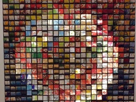
I have always been impressed by kinetic art, especially the mirrors of artist Daniel Rozin.
I wanted to try to make one, too.
I started with a table of 160 cocktail umbrellas, then the one visible here.
576 SPMSA 330 servo motors (24x24) controlled by an Arduino Mega board and 24 Pololu Maestros.
An OV7670 camera was also used to move the pads according to what is visible in front of the camera like a mirror. Robert Chin's book "Beginning Arduino Ov7670 Camera Development" was of great use.
The pads and the servo motor brackets were printed in ABS with a Zmorph.
8 months later you can see the result:
// pour voir la photo .yuv utliser le terminal et ecrire:
// ffmpeg -f rawvideo -s 86x72 -pix_fmt yuyv422 -i /QQVGA0.YUV -f image2 -vcodec png /outputfile.png
// le format utilis pour la camra est qqcif 86x72, les valeurs pour qqcif on t change dans le format qqvga
#include "matrixpixel.h"
#include <Wire.h>// pour communccation I2C pour parametrer la camera
#include <SD.h>// pour la carte SD
#include <SPI.h>// bus spi serie pour la maestro et bluetooth
#include <LiquidCrystal.h>// pour le LCD afficheur
LiquidCrystal lcd(4, 6, 10, 11, 12, 13);// initialize the library with the numbers of the interface pins
#include "LcDef.h"// definition des valeurs de registre de la camera
#include <PololuMaestro.h> // pour contrler les cartes servos
#ifdef SERIAL_PORT_HARDWARE_OPEN
#define maestroSerial SERIAL_PORT_HARDWARE_OPEN
#else
#include <SoftwareSerial.h>
SoftwareSerial maestroSerial(19, 18);
#endif
//* Next, create a Maestro object using the serial port.
MiniMaestro maestro0(maestroSerial,255,12);
MiniMaestro maestro1(maestroSerial,255,13);
MiniMaestro maestro2(maestroSerial,255,14);
MiniMaestro maestro3(maestroSerial,255,15);
MiniMaestro maestro4(maestroSerial,255,16);
MiniMaestro maestro5(maestroSerial,255,17);
MiniMaestro maestro6(maestroSerial,255,18);
MiniMaestro maestro7(maestroSerial,255,19);
MiniMaestro maestro8(maestroSerial,255,20);
MiniMaestro maestro9(maestroSerial,255,21);
MiniMaestro maestro10(maestroSerial,255,22);
MiniMaestro maestro11(maestroSerial,255,23);
MiniMaestro maestro12(maestroSerial,255,24);
MiniMaestro maestro13(maestroSerial,255,25);
MiniMaestro maestro14(maestroSerial,255,26);
MiniMaestro maestro15(maestroSerial,255,27);
MiniMaestro maestro16(maestroSerial,255,28);
MiniMaestro maestro17(maestroSerial,255,29);
MiniMaestro maestro18(maestroSerial,255,30);
MiniMaestro maestro19(maestroSerial,255,31);
MiniMaestro maestro20(maestroSerial,255,32);
MiniMaestro maestro21(maestroSerial,255,33);
MiniMaestro maestro22(maestroSerial,255,34);
MiniMaestro maestro23(maestroSerial,255,35);
MiniMaestro device[24]{maestro0,maestro1,maestro2,maestro3,maestro4,maestro5,maestro6,maestro7,maestro8,maestro9,maestro10,maestro11,maestro12,maestro13,maestro14,maestro15,maestro16,maestro17,maestro18,maestro19,maestro20,maestro21,maestro22,maestro23};
//limite ne pas dpasser au tableau sinon le servos,les bras, les pices mobiles sont forces
int degremin=25;// la plaque est tourne contre le haut
int degremax=150;// la plaque est tourne contre le bas
//limite ne pas dpasser par les servos sinon ils cassent, valeur plus extremes encore que degremin et degremax
int valeurmax=map(degremax,0,180,2752,9600);// pour limiter les mouvements de degremin 160 degrmax 2400,8000 sont les valeurs min et max a donner auxservos pour 0 et 180 degrs
int valeurmin=map(degremin,0,180,2752,9600);// pour limiter les mouvements de 30 160 degrs 2400,8000 sont les valeurs min et max a donner auxservos pour 0 et 180 degrs
int valeur=valeurmin;
const int chipSelect = 53;
const int HardwareSSPin = 53; // For Arduino Mega
// Serial Input
const int BUFFERLENGTH = 255;
char IncomingByte[BUFFERLENGTH]; // for incoming serial data
// VGA Default
int PHOTO_WIDTH = 640;
int PHOTO_HEIGHT = 480;
int PHOTO_BYTES_PER_PIXEL = 2;
// Command and Parameter related Strings pour le choix de la balance des blancs, du temps de pose et du gain, du contour et du bruit, du niveau de noir
String RawCommandLine = "";
String Command = "QVGA";// mais en fait c'est qqcif 72x86
String FPSParam = "ThirtyFPS";//"NightMode" ou"ThirtyFPS"
String AWBParam = "AAWB";//automatic white balance "AAWB" ou"SAWB"// AAWB est meilleur avec le tableau dans l'atelier avec peu de lumire
String AECParam = "AveAEC";//automatic exposure control "AveAEC"(average) ou"HistAEC"(histogramme)// AveAEC est bien meilleur avec le tableau
String YUVMatrixParam = "YUVMatrixOn";// ne rien mettre si on ne veut pas ou "YUVMatrixOn"
String DenoiseParam = "DenoiseYes";//"DenoiseYes" ou"DenoiseNo"// un peu les deux pareils
String EdgeParam = "EdgeYes";//"EdgeYes" ou"EdgeNo"// un peu les deux pareils
String ABLCParam = "AblcOn";//"AblcOFF" ou"AblcON"// mieux avce AblOFF automatic black level control,dans la pnombre
byte angle[24][24];// on ne peut pas avoir un tableau de byte car on additionne les valeurs de 9 pixels la fois donc 9*255, mais si on divise pixeldata/9 a fonctionne mais un peu moins prcis
byte angleetalon90[24][24];
//byte angleetalonmax[24][24];
byte anglebefore[24][24];
int comptage = 0;
boolean firstpicture=true;
boolean macro=false;
//// variable pour input
const byte numChars = 32;
char receivedChars[numChars];
char tempChars[numChars]; // temporary array for use when parsing
char messageFromPC[numChars] = {0};// variables to hold the parsed data
int integer0FromPC = 0;
int integer1FromPC = 0;
int integer2FromPC = 0;
int integer3FromPC = 0;
boolean newData = false;
//// variable pour menu ett bouton
int JoyStick_X = A0; //PS2 joystick X-axis is defined, ANALOG IN of Pin0 VRX sur A0
int JoyStick_Y = A1; //PS2 joystick Y axis is defined, ANALOG IN of Pin1 VRY sur A1
int JoyStick_Z = 2; //Defined PS2 joystick Z axis, pin2 SW sur 2 digital (pas analogique)
int potentiometre=A7;// le pot est dans le pin analogique no 7 le pin du milieu du potentiometre sur A7
int btpot;
int btx;
int bty;
int btz;
byte colonne=0;
byte ligne=0;
int nomenualain=0;
byte colonneavant=0;
byte ligneavant=0;
//// fin de variable pour menu ett bouton
enum ResolutionType
{
VGA,
VGAP,
QVGA,
QQVGA,
None
};
ResolutionType Resolution = None;
// Camera input/output pin connection to Arduino
#define WRST 25 // Output Write Pointer Reset// ATTENTION sur le manuel 25 et 22 sont intervertis
#define RRST 23 // Output Read Pointer Reset
#define WEN 24 // Output Write Enable
#define VSYNC 22 // Input Vertical Sync marking frame capture // ATTENTION sur le manuel 25 et 22 sont intervertis
#define RCLK 26 // Output FIFO buffer output clock
// set OE to low gnd
// FIFO Ram input pins
#define DO7 28
#define DO6 29
#define DO5 30
#define DO4 31
#define DO3 32
#define DO2 33
#define DO1 34
#define DO0 35
// SDCARD
// MISO, MOSI, and SCK are also available in a consistent physical location on the ICSP header;
// this is useful, for example, in designing a shield that works on the Uno and the Mega.
// On the Arduino Mega, this is
// 50 (MISO)
// 51 (MOSI)
// 52 (SCK)
// 53 (SS)
// VCC sur 5V
//GND sur GND
File myFile;// myFile=le fichier qu'on va lire sur la carte SD qui contient les valeurs
byte ReadRegisterValue(int RegisterAddress)
{
byte data = 0;
Wire.beginTransmission(OV7670_I2C_ADDRESS);
Wire.write(RegisterAddress);
Wire.endTransmission();
Wire.requestFrom(OV7670_I2C_ADDRESS, 1);
while(Wire.available() < 1);
data = Wire.read();
return data;
}
void ReadRegisters()
{
byte data = 0;
data = ReadRegisterValue(CLKRC);
Serial.print(F("CLKRC = "));
Serial.println(data,HEX);
data = ReadRegisterValue(COM7);
Serial.print(F("COM7 = "));
Serial.println(data,HEX);
data = ReadRegisterValue(COM3);
Serial.print(F("COM3 = "));
Serial.println(data,HEX);
data = ReadRegisterValue(COM14);
Serial.print(F("COM14 = "));
Serial.println(data,HEX);
data = ReadRegisterValue(SCALING_XSC);
Serial.print(F("SCALING_XSC = "));
Serial.println(data,HEX);
data = ReadRegisterValue(SCALING_YSC);
Serial.print(F("SCALING_YSC = "));
Serial.println(data,HEX);
data = ReadRegisterValue(SCALING_DCWCTR);
Serial.print(F("SCALING_DCWCTR = "));
Serial.println(data,HEX);
data = ReadRegisterValue(SCALING_PCLK_DIV);
Serial.print(F("SCALING_PCLK_DIV = "));
Serial.println(data,HEX);
data = ReadRegisterValue(SCALING_PCLK_DELAY);
Serial.print(F("SCALING_PCLK_DELAY = "));
Serial.println(data,HEX);
//data = ReadRegisterValue(COM10);
//Serial.print(F("COM10 (Vsync Polarity) = "));
//Serial.println(data,HEX);
// default value D
data = ReadRegisterValue(TSLB);
Serial.print(F("TSLB (YUV Order- Higher Bit, Bit[3]) = "));
Serial.println(data,HEX);
// default value 88
data = ReadRegisterValue(COM13);
Serial.print(F("COM13 (YUV Order - Lower Bit, Bit[1]) = "));
Serial.println(data,HEX);
data = ReadRegisterValue(COM17);
Serial.print(F("COM17 (DSP Color Bar Selection) = "));
Serial.println(data,HEX);
data = ReadRegisterValue(COM4);
Serial.print(F("COM4 (works with COM 17) = "));
Serial.println(data,HEX);
data = ReadRegisterValue(COM15);
Serial.print(F("COM15 (COLOR FORMAT SELECTION) = "));
Serial.println(data,HEX);
data = ReadRegisterValue(COM11);
Serial.print(F("COM11 (Night Mode) = "));
Serial.println(data,HEX);
data = ReadRegisterValue(COM8);
Serial.print(F("COM8 (Color Control, AWB) = "));
Serial.println(data,HEX);
data = ReadRegisterValue(HAECC7);
Serial.print(F("HAECC7 (AEC Algorithm Selection) = "));
Serial.println(data,HEX);
data = ReadRegisterValue(GFIX);
Serial.print(F("GFIX = "));
Serial.println(data,HEX);
// Window Output
data = ReadRegisterValue(HSTART);
Serial.print(F("HSTART = "));
Serial.println(data,HEX);
//Serial.print(F(", "));
//Serial.println(data, DEC);
data = ReadRegisterValue(HSTOP);
Serial.print(F("HSTOP = "));
Serial.println(data,HEX);
data = ReadRegisterValue(HREF);
Serial.print(F("HREF = "));
Serial.println(data,HEX);
data = ReadRegisterValue(VSTRT);
Serial.print(F("VSTRT = "));
Serial.println(data,HEX);
data = ReadRegisterValue(VSTOP);
Serial.print(F("VSTOP = "));
Serial.println(data,HEX);
data = ReadRegisterValue(VREF);
Serial.print(F("VREF = "));
Serial.println(data,HEX);
}
void ResetCameraRegisters()
{
// Reset Camera Registers
// Reading needed to prevent error
byte data = ReadRegisterValue(COM7);
int result = OV7670WriteReg(COM7, COM7_VALUE_RESET );
String sresult = ParseI2CResult(result);
Serial.println("RESETTING ALL REGISTERS BY SETTING COM7 REGISTER to 0x80: " + sresult);
// Delay at least 500ms
delay(500);
}
// Main Call to Setup the ov7670 Camera
void SetupCamera()
{
Serial.println(F("In SetupCamera() ..."));
InitializeOV7670Camera();
}
void InitializeOV7670Camera()
{
Serial.println(F("Initializing OV7670 Camera ..."));
//Set WRST to 0 and RRST to 0 , 0.1ms after power on.
int DurationMicroSecs = 1;// mais on peut mettre aussi 0 a va aussi
// Set mode for pins wither input or output
pinMode(WRST , OUTPUT);
pinMode(RRST , OUTPUT);
pinMode(WEN , OUTPUT);
pinMode(VSYNC, INPUT);
pinMode(RCLK , OUTPUT);
// FIFO Ram output pins
pinMode(DO7 , INPUT);
pinMode(DO6 , INPUT);
pinMode(DO5 , INPUT);
pinMode(DO4 , INPUT);
pinMode(DO3 , INPUT);
pinMode(DO2 , INPUT);
pinMode(DO1 , INPUT);
pinMode(DO0 , INPUT);
// Delay 1 ms
delay(1);
PulseLowEnabledPin(WRST, DurationMicroSecs);
//PulseLowEnabledPin(RRST, DurationMicroSecs);
// Need to clock the fifo manually to get it to reset
digitalWrite(RRST, LOW);
PulsePin(RCLK, DurationMicroSecs);
PulsePin(RCLK, DurationMicroSecs);
digitalWrite(RRST, HIGH);
}
void SetupCameraAdvancedAutoWhiteBalanceConfig()// utilis dans le format que j'utilise dans le choix de AAWB
{
int result = 0;
String sresult = "";
Serial.println(F("........... Setting Camera Advanced Auto White Balance Configs ........"));
result = OV7670WriteReg(AWBC1, AWBC1_VALUE);
sresult = ParseI2CResult(result);
Serial.print(F("AWBC1: "));
Serial.println(sresult);
result = OV7670WriteReg(AWBC2, AWBC2_VALUE);
sresult = ParseI2CResult(result);
Serial.print(F("AWBC2: "));
Serial.println(sresult);
result = OV7670WriteReg(AWBC3, AWBC3_VALUE);
sresult = ParseI2CResult(result);
Serial.print(F("AWBC3: "));
Serial.println(sresult);
result = OV7670WriteReg(AWBC4, AWBC4_VALUE);
sresult = ParseI2CResult(result);
Serial.print(F("AWBC4: "));
Serial.println(sresult);
result = OV7670WriteReg(AWBC5, AWBC5_VALUE);
sresult = ParseI2CResult(result);
Serial.print(F("AWBC5: "));
Serial.println(sresult);
result = OV7670WriteReg(AWBC6, AWBC6_VALUE);
sresult = ParseI2CResult(result);
Serial.print(F("AWBC6: "));
Serial.println(sresult);
result = OV7670WriteReg(AWBC7, AWBC7_VALUE);
sresult = ParseI2CResult(result);
Serial.print(F("AWBC7: "));
Serial.println(sresult);
result = OV7670WriteReg(AWBC8, AWBC8_VALUE);
sresult = ParseI2CResult(result);
Serial.print(F("AWBC8: "));
Serial.println(sresult);
result = OV7670WriteReg(AWBC9, AWBC9_VALUE);
sresult = ParseI2CResult(result);
Serial.print(F("AWBC9: "));
Serial.println(sresult);
result = OV7670WriteReg(AWBC10, AWBC10_VALUE);
sresult = ParseI2CResult(result);
Serial.print(F("AWBC10: "));
Serial.println(sresult);
result = OV7670WriteReg(AWBC11, AWBC11_VALUE);
sresult = ParseI2CResult(result);
Serial.print(F("AWBC11: "));
Serial.println(sresult);
result = OV7670WriteReg(AWBC12, AWBC12_VALUE);
sresult = ParseI2CResult(result);
Serial.print(F("AWBC12: "));
Serial.println(sresult);
result = OV7670WriteReg(AWBCTR3, AWBCTR3_VALUE);
sresult = ParseI2CResult(result);
Serial.print(F("AWBCTR3: "));
Serial.println(sresult);
result = OV7670WriteReg(AWBCTR2, AWBCTR2_VALUE);
sresult = ParseI2CResult(result);
Serial.print(F("AWBCTR2: "));
Serial.println(sresult);
result = OV7670WriteReg(AWBCTR1, AWBCTR1_VALUE);
sresult = ParseI2CResult(result);
Serial.print(F("AWBCTR1: "));
Serial.println(sresult);
}
void SetupCameraUndocumentedRegisters()// utilis dans le format que j'utilise
{
// Write(0xb0,0x84); //adding this improve the color a little bit
int result = 0;
String sresult = "";
Serial.println(F("........... Setting Camera Undocumented Registers ........"));
result = OV7670WriteReg(0xB0, 0x84);
sresult = ParseI2CResult(result);
Serial.print(F("Setting B0 UNDOCUMENTED register to 0x84:= "));
Serial.println(sresult);
}
void SetupCameraFor30FPS()// utilis dans le format que j'utilise
{
int result = 0;
String sresult = "";
Serial.println(F("........... Setting Camera to 30 FPS ........"));
result = OV7670WriteReg(CLKRC, CLKRC_VALUE_30FPS);
sresult = ParseI2CResult(result);
Serial.print(F("CLKRC: "));
Serial.println(sresult);
result = OV7670WriteReg(DBLV, DBLV_VALUE_30FPS);
sresult = ParseI2CResult(result);
Serial.print(F("DBLV: "));
Serial.println(sresult);
result = OV7670WriteReg(EXHCH, EXHCH_VALUE_30FPS);
sresult = ParseI2CResult(result);
Serial.print(F("EXHCH: "));
Serial.println(sresult);
result = OV7670WriteReg(EXHCL, EXHCL_VALUE_30FPS);
sresult = ParseI2CResult(result);
Serial.print(F("EXHCL: "));
Serial.println(sresult);
result = OV7670WriteReg(DM_LNL, DM_LNL_VALUE_30FPS);
sresult = ParseI2CResult(result);
Serial.print(F("DM_LNL: "));
Serial.println(sresult);
result = OV7670WriteReg(DM_LNH, DM_LNH_VALUE_30FPS);
sresult = ParseI2CResult(result);
Serial.print(F("DM_LNH: "));
Serial.println(sresult);
result = OV7670WriteReg(COM11, COM11_VALUE_30FPS);
sresult = ParseI2CResult(result);
Serial.print(F("COM11: "));
Serial.println(sresult);
}
void SetupCameraABLC()// utilis dans le format que j'utilise automatic black level calibration
{
int result = 0;
String sresult = "";
// If ABLC is off then return otherwise
// turn on ABLC.
if (ABLCParam == "AblcOFF")
{
return;
}
Serial.println(F("........ Setting Camera ABLC ......."));
result = OV7670WriteReg(ABLC1, ABLC1_VALUE);
sresult = ParseI2CResult(result);
Serial.print(F("ABLC1: "));
Serial.println(sresult);
result = OV7670WriteReg(THL_ST, THL_ST_VALUE);
sresult = ParseI2CResult(result);
Serial.print(F("THL_ST: "));
Serial.println(sresult);
}
void SetupCameraAverageBasedAECAGC()// voir chapitre 3.3.4.1 de implementation-guide// utilis dans le format que j'utilise dans le choix de AveAEC
{
int result = 0;
String sresult = "";
Serial.println(F("-------------- Setting Camera Average Based AEC/AGC Registers ---------------"));
// il y a deux zones: la controlzone en dehors de laquelle aec(automatique exposure)et agc (automatic gain) sont augment ou diminu par de large pas
// une fois dans la controlezone mais en dehors de la stable operatingregion les pas sont pkus petits, puis une fois dans la stable operating region il n'ya plus de changement de aec ni de agc
// on peut donc dfinir les limites sup et inf des deux zones
result = OV7670WriteReg(AEW, AEW_VALUE);// stable operating region upper limit
sresult = ParseI2CResult(result);
Serial.print(F("AEW: "));
Serial.println(sresult);
result = OV7670WriteReg(AEB, AEB_VALUE);// stable operating region lower limit
sresult = ParseI2CResult(result);
Serial.print(F("AEB: "));
Serial.println(sresult);
result = OV7670WriteReg(VPT, VPT_VALUE);// control zone upper limit (VPT[7:4]) et lower limit sur VPT[3:0]
sresult = ParseI2CResult(result);
Serial.print(F("VPT: "));
Serial.println(sresult);
result = OV7670WriteReg(HAECC7, HAECC7_VALUE_AVERAGE_AEC_ON);// average luminance calculation window (full frame ou center halfframe, ou ceter quarter frame)
sresult = ParseI2CResult(result);
Serial.print(F("HAECC7: "));
Serial.println(sresult);
}
void SetCameraHistogramBasedAECAGC()// utilis dans le format que j'utilise dans le choix de HistAEC
{
int result = 0;
String sresult = "";
Serial.println(F("-------------- Setting Camera Histogram Based AEC/AGC Registers ---------------"));
result = OV7670WriteReg(AEW, AEW_VALUE);
sresult = ParseI2CResult(result);
Serial.print(F("AEW: "));
Serial.println(sresult);
result = OV7670WriteReg(AEB, AEB_VALUE);
sresult = ParseI2CResult(result);
Serial.print(F("AEB: "));
Serial.println(sresult);
result = OV7670WriteReg(HAECC1, HAECC1_VALUE);
sresult = ParseI2CResult(result);
Serial.print(F("HAECC1: "));
Serial.println(sresult);
result = OV7670WriteReg(HAECC2, HAECC2_VALUE);
sresult = ParseI2CResult(result);
Serial.print(F("HAECC2: "));
Serial.println(sresult);
result = OV7670WriteReg(HAECC3, HAECC3_VALUE);
sresult = ParseI2CResult(result);
Serial.print(F("HAECC3: "));
Serial.println(sresult);
result = OV7670WriteReg(HAECC4, HAECC4_VALUE);
sresult = ParseI2CResult(result);
Serial.print(F("HAECC4: "));
Serial.println(sresult);
result = OV7670WriteReg(HAECC5, HAECC5_VALUE);
sresult = ParseI2CResult(result);
Serial.print(F("HAECC5: "));
Serial.println(sresult);
result = OV7670WriteReg(HAECC6, HAECC6_VALUE);
sresult = ParseI2CResult(result);
Serial.print(F("HAECC6: "));
Serial.println(sresult);
result = OV7670WriteReg(HAECC7, HAECC7_VALUE_HISTOGRAM_AEC_ON);
sresult = ParseI2CResult(result);
Serial.print(F("HAECC7: "));
Serial.println(sresult);
}
void SetupCameraNightMode()// utilis dans le format que j'utilise, dans le choix de FPS mode
{
int result = 0;
String sresult = "";
Serial.println(F("......... Turning NIGHT MODE ON ........"));
result = OV7670WriteReg(CLKRC, CLKRC_VALUE_NIGHTMODE_AUTO);
sresult = ParseI2CResult(result);
Serial.print(F("CLKRC: "));
Serial.println(sresult);
result = OV7670WriteReg(COM11, COM11_VALUE_NIGHTMODE_AUTO);
sresult = ParseI2CResult(result);
Serial.print(F("COM11: "));
Serial.println(sresult);
}
void SetupCameraSimpleAutomaticWhiteBalance()// utilis dans le format que j'utilise dans le choix de SAWB
{
/*
i2c_salve_Address = 0x42;
write_i2c(0x13, 0xe7); //AWB on
write_i2c(0x6f, 0x9f); // Simple AWB
*/
int result = 0;
String sresult = "";
Serial.println(F("........... Setting Camera to Simple AWB ........"));
// COM8
//result = OV7670WriteReg(0x13, 0xE7);
result = OV7670WriteReg(COM8, COM8_VALUE_AWB_ON);// simple automatic white balance
sresult = ParseI2CResult(result);
Serial.print(F("COM8(0x13): "));
Serial.println(sresult);
// AWBCTR0
//result = OV7670WriteReg(0x6f, 0x9f);
result = OV7670WriteReg(AWBCTR0, AWBCTR0_VALUE_NORMAL);// simple automatic white balance
sresult = ParseI2CResult(result);
Serial.print(F("AWBCTR0 Control Register 0(0x6F): "));
Serial.println(sresult);
}
void SetupCameraAdvancedAutomaticWhiteBalance()// utilis dans le format que j'utilise dans le choix de AAWB
{
int result = 0;
String sresult = "";
Serial.println(F("........... Setting Camera to Advanced AWB ........"));
// AGC, AWB, and AEC Enable
result = OV7670WriteReg(0x13, 0xE7);//0xE7 normalement , j'ai mis E6 pour desactiver le AEC
sresult = ParseI2CResult(result);
Serial.print(F("COM8(0x13): "));
Serial.println(sresult);
// AWBCTR0
result = OV7670WriteReg(0x6f, 0x9E);
sresult = ParseI2CResult(result);
Serial.print(F("AWB Control Register 0(0x6F): "));
Serial.println(sresult);
}
void SetupCameraGain()// utilis dans le format que j'utilise dans le choix de AWB SAWB ou AAWB
{
int result = 0;
String sresult = "";
Serial.println(F("........... Setting Camera Gain ........"));
// Set Maximum Gain
//result = OV7670WriteReg(COM9, COM9_VALUE_MAX_GAIN_128X);
result = OV7670WriteReg(COM9, COM9_VALUE_4XGAIN);
//result = OV7670WriteReg(COM9, 0x18);
sresult = ParseI2CResult(result);
Serial.print(F("COM9: "));
Serial.println(sresult);
// Set Blue Gain
//{ REG_BLUE, 0x40 },
result = OV7670WriteReg(BLUE, BLUE_VALUE);
sresult = ParseI2CResult(result);
Serial.print(F("BLUE GAIN: "));
Serial.println(sresult);
// Set Red Gain
//{ REG_RED, 0x60 },
result = OV7670WriteReg(RED, RED_VALUE);
sresult = ParseI2CResult(result);
Serial.print(F("RED GAIN: "));
Serial.println(sresult);
// Set Green Gain
//{ 0x6a, 0x40 },
result = OV7670WriteReg(GGAIN, GGAIN_VALUE);
sresult = ParseI2CResult(result);
Serial.print(F("GREEN GAIN: "));
Serial.println(sresult);
// Enable AWB Gain
// REG_COM16 0x41 /* Control 16 */
// COM16_AWBGAIN 0x08 /* AWB gain enable */
// { REG_COM16, COM16_AWBGAIN },
result = OV7670WriteReg(COM16, COM16_VALUE);
sresult = ParseI2CResult(result);
Serial.print(F("COM16(ENABLE GAIN): "));
Serial.println(sresult);
}
void SetCameraSaturationControl()// utilis dans le format que j'utilise
{
int result = 0;
String sresult = "";
Serial.println(F("........... Setting Camera Saturation Level ........"));
result = OV7670WriteReg(SATCTR, SATCTR_VALUE);
sresult = ParseI2CResult(result);
Serial.print(F("SATCTR: "));
Serial.println(sresult);
}
void SetCameraColorMatrixYUV()// utilis dans le format que j'utilise
{
int result = 0;
String sresult = "";
Serial.println(F("........... Setting Camera Color Matrix for YUV ........"));
result = OV7670WriteReg(MTX1, MTX1_VALUE);
sresult = ParseI2CResult(result);
Serial.print(F("MTX1: "));
Serial.println(sresult);
result = OV7670WriteReg(MTX2, MTX2_VALUE);
sresult = ParseI2CResult(result);
Serial.print(F("MTX2: "));
Serial.println(sresult);
result = OV7670WriteReg(MTX3, MTX3_VALUE);
sresult = ParseI2CResult(result);
Serial.print(F("MTX3: "));
Serial.println(sresult);
result = OV7670WriteReg(MTX4, MTX4_VALUE);
sresult = ParseI2CResult(result);
Serial.print(F("MTX4: "));
Serial.println(sresult);
result = OV7670WriteReg(MTX5, MTX5_VALUE);
sresult = ParseI2CResult(result);
Serial.print(F("MTX5: "));
Serial.println(sresult);
result = OV7670WriteReg(MTX6, MTX6_VALUE);
sresult = ParseI2CResult(result);
Serial.print(F("MTX6: "));
Serial.println(sresult);
result = OV7670WriteReg(CONTRAS, CONTRAS_VALUE);
sresult = ParseI2CResult(result);
Serial.print(F("CONTRAS: "));
Serial.println(sresult);
result = OV7670WriteReg(MTXS, MTXS_VALUE);
sresult = ParseI2CResult(result);
Serial.print(F("MTXS: "));
Serial.println(sresult);
}
void SetCameraFPSMode()// utilis dans le format que j'utilise
{
// Set FPS for Camera
if (FPSParam == "ThirtyFPS")
{
SetupCameraFor30FPS();
}
else
if (FPSParam == "NightMode")
{
SetupCameraNightMode();
}
}
void SetCameraAEC()// utilis dans le format que j'utilise
{
// Process AEC
if (AECParam == "AveAEC")
{
// Set Camera's Average AEC/AGC Parameters
SetupCameraAverageBasedAECAGC();
}
else
if (AECParam == "HistAEC")
{
// Set Camera AEC algorithim to Histogram
SetCameraHistogramBasedAECAGC();
}
}
void SetupCameraAWB()// utilis dans le format que j'utilise
{
// Set AWB Mode
if (AWBParam == "SAWB")
{
// Set Simple Automatic White Balance
SetupCameraSimpleAutomaticWhiteBalance(); // OK
// Set Gain Config
SetupCameraGain();
}
else
if (AWBParam == "AAWB")
{
// Set Advanced Automatic White Balance
SetupCameraAdvancedAutomaticWhiteBalance(); // ok
// Set Camera Automatic White Balance Configuration
SetupCameraAdvancedAutoWhiteBalanceConfig(); // ok
// Set Gain Config
SetupCameraGain();
}
}
void SetupCameraDenoise()
{
int result = 0;
String sresult = "";
Serial.println(F("........... Setting Camera Denoise ........"));
result = OV7670WriteReg(DNSTH, DNSTH_VALUE);
sresult = ParseI2CResult(result);
Serial.print(F("DNSTH: "));
Serial.println(sresult);
result = OV7670WriteReg(REG77, REG77_VALUE);
sresult = ParseI2CResult(result);
Serial.print(F("REG77: "));
Serial.println(sresult);
}
void SetupCameraEdgeEnhancement()
{
int result = 0;
String sresult = "";
Serial.println(F("........... Setting Camera Edge Enhancement ........"));
result = OV7670WriteReg(EDGE, EDGE_VALUE);
sresult = ParseI2CResult(result);
Serial.print(F("EDGE: "));
Serial.println(sresult);
result = OV7670WriteReg(REG75, REG75_VALUE);
sresult = ParseI2CResult(result);
Serial.print(F("REG75: "));
Serial.println(sresult);
result = OV7670WriteReg(REG76, REG76_VALUE);
sresult = ParseI2CResult(result);
Serial.print(F("REG76: "));
Serial.println(sresult);
}
void SetupCameraDenoiseEdgeEnhancement()// utilis dans le format que j'utilise
{
int result = 0;
String sresult = "";
if ((DenoiseParam == "DenoiseYes")&&
(EdgeParam == "EdgeYes"))
{
SetupCameraDenoise();
SetupCameraEdgeEnhancement();
result = OV7670WriteReg(COM16, COM16_VALUE_DENOISE_ON__EDGE_ENHANCEMENT_ON__AWBGAIN_ON);
sresult = ParseI2CResult(result);
Serial.print(F("COM16: "));
Serial.println(sresult);
}
else
if ((DenoiseParam == "DenoiseYes")&&
(EdgeParam == "EdgeNo"))
{
SetupCameraDenoise();
result = OV7670WriteReg(COM16, COM16_VALUE_DENOISE_ON__EDGE_ENHANCEMENT_OFF__AWBGAIN_ON);
sresult = ParseI2CResult(result);
Serial.print(F("COM16: "));
Serial.println(sresult);
}
else
if ((DenoiseParam == "DenoiseNo")&&
(EdgeParam == "EdgeYes"))
{
SetupCameraEdgeEnhancement();
result = OV7670WriteReg(COM16, COM16_VALUE_DENOISE_OFF__EDGE_ENHANCEMENT_ON__AWBGAIN_ON);
sresult = ParseI2CResult(result);
Serial.print(F("COM16: "));
Serial.println(sresult);
}
}
/*
void SetCameraGamma()
{
int result = 0;
String sresult = "";
Serial.println(F("........... Setting Camera Gamma ........"));
result = OV7670WriteReg(SLOP, SLOP_VALUE);
sresult = ParseI2CResult(result);
Serial.print(F("SLOP: "));
Serial.println(sresult);
result = OV7670WriteReg(GAM1, GAM1_VALUE);
sresult = ParseI2CResult(result);
Serial.print(F("GAM1: "));
Serial.println(sresult);
result = OV7670WriteReg(GAM2, GAM2_VALUE);
sresult = ParseI2CResult(result);
Serial.print(F("GAM2: "));
Serial.println(sresult);
result = OV7670WriteReg(GAM3, GAM3_VALUE);
sresult = ParseI2CResult(result);
Serial.print(F("GAM3: "));
Serial.println(sresult);
result = OV7670WriteReg(GAM4, GAM4_VALUE);
sresult = ParseI2CResult(result);
Serial.print(F("GAM4: "));
Serial.println(sresult);
result = OV7670WriteReg(GAM5, GAM5_VALUE);
sresult = ParseI2CResult(result);
Serial.print(F("GAM5: "));
Serial.println(sresult);
result = OV7670WriteReg(GAM6, GAM6_VALUE);
sresult = ParseI2CResult(result);
Serial.print(F("GAM6: "));
Serial.println(sresult);
result = OV7670WriteReg(GAM7, GAM7_VALUE);
sresult = ParseI2CResult(result);
Serial.print(F("GAM7: "));
Serial.println(sresult);
result = OV7670WriteReg(GAM8, GAM8_VALUE);
sresult = ParseI2CResult(result);
Serial.print(F("GAM8: "));
Serial.println(sresult);
result = OV7670WriteReg(GAM9, GAM9_VALUE);
sresult = ParseI2CResult(result);
Serial.print(F("GAM9: "));
Serial.println(sresult);
result = OV7670WriteReg(GAM10, GAM10_VALUE);
sresult = ParseI2CResult(result);
Serial.print(F("GAM10: "));
Serial.println(sresult);
result = OV7670WriteReg(GAM11, GAM11_VALUE);
sresult = ParseI2CResult(result);
Serial.print(F("GAM11: "));
Serial.println(sresult);
result = OV7670WriteReg(GAM12, GAM12_VALUE);
sresult = ParseI2CResult(result);
Serial.print(F("GAM12: "));
Serial.println(sresult);
result = OV7670WriteReg(GAM13, GAM13_VALUE);
sresult = ParseI2CResult(result);
Serial.print(F("GAM13: "));
Serial.println(sresult);
result = OV7670WriteReg(GAM14, GAM14_VALUE);
sresult = ParseI2CResult(result);
Serial.print(F("GAM14: "));
Serial.println(sresult);
result = OV7670WriteReg(GAM15, GAM15_VALUE);
sresult = ParseI2CResult(result);
Serial.print(F("GAM15: "));
Serial.println(sresult);
}
*/
void SetupCameraArrayControl()// il semble que pas utilis dans le format que j'utilise
{
int result = 0;
String sresult = "";
Serial.println(F("........... Setting Camera Array Control ........"));
result = OV7670WriteReg(CHLF, CHLF_VALUE);
sresult = ParseI2CResult(result);
Serial.print(F("CHLF: "));
Serial.println(sresult);
result = OV7670WriteReg(ARBLM, ARBLM_VALUE);
sresult = ParseI2CResult(result);
Serial.print(F("ARBLM: "));
Serial.println(sresult);
}
void SetupCameraADCControl()// utilis dans le format que j'utilise
{
int result = 0;
String sresult = "";
Serial.println(F("........... Setting Camera ADC Control ........"));
result = OV7670WriteReg(ADCCTR1, ADCCTR1_VALUE);
sresult = ParseI2CResult(result);
Serial.print(F("ADCCTR1: "));
Serial.println(sresult);
result = OV7670WriteReg(ADCCTR2, ADCCTR2_VALUE);
sresult = ParseI2CResult(result);
Serial.print(F("ADCCTR2: "));
Serial.println(sresult);
result = OV7670WriteReg(ADC, ADC_VALUE);
sresult = ParseI2CResult(result);
Serial.print(F("ADC: "));
Serial.println(sresult);
result = OV7670WriteReg(ACOM, ACOM_VALUE);
sresult = ParseI2CResult(result);
Serial.print(F("ACOM: "));
Serial.println(sresult);
result = OV7670WriteReg(OFON, OFON_VALUE);
sresult = ParseI2CResult(result);
Serial.print(F("OFON: "));
Serial.println(sresult);
}
// special effects modify the MANU and MANV registers to override the computed values
// the TSLB is setup for various bit patters having to do with negative etc.
void specialEffects(){
byte r_tslb = 0x10;// pour black and white
byte r_manu = 0x80;// pour black and white
byte r_manv = 0x80;// pour black and white
// byte r_tslb = 0x30;// pour black and white negative
// byte r_manu = 0x80;// pour black and white negative
// byte r_manv = 0x80;// pour black and white negative
//
//
// byte r_tslb = 0x20;// color negative
// byte r_manu = 0x80;// color negative
// byte r_manv = 0x80;// color negative
byte temp;
temp = ReadRegisterValue(TSLB);
temp = temp & 0xCF; // mask out bits 5 & 4
temp = temp | r_tslb;
OV7670WriteReg(TSLB,temp);
OV7670WriteReg(MANU,r_manu);
OV7670WriteReg(MANV,r_manv);
}
//********************************************************************************************************
//********************************************************************************************************
//********************************************************************************************************
//********************************************************************************************************
//********************************************************************************************************
void SetupOV7670ForQQVGAYUV()// mais en fait c'est qqcif (86x72)qui sera configur
{
int result = 0;
String sresult = "";
Serial.println(F("--------------------------- Setting Camera for QQVGA YUV ---------------------------"));
PHOTO_WIDTH = 86;// pour qqcif avec 86 au lieu de 88
PHOTO_HEIGHT = 72;
PHOTO_BYTES_PER_PIXEL = 2;
Serial.print(F("Photo Width = "));
Serial.println(PHOTO_WIDTH);
Serial.print(F("Photo Height = "));
Serial.println(PHOTO_HEIGHT);
Serial.print(F("Bytes Per Pixel = "));
Serial.println(PHOTO_BYTES_PER_PIXEL);
Serial.println(F("........... Setting Basic QQVGA Parameters ........"));
result = OV7670WriteReg(CLKRC, CLKRC_VALUE_QQVGA);
sresult = ParseI2CResult(result);
Serial.print(F("CLKRC: "));
Serial.println(sresult);
result = OV7670WriteReg(COM7, COM7_VALUE_QQVGA );
//result = OV7670WriteReg(COM7, COM7_VALUE_QQVGA_COLOR_BAR );
sresult = ParseI2CResult(result);
Serial.print(F("COM7: "));
Serial.println(sresult);
result = OV7670WriteReg(COM3, COM3_VALUE_QQVGA);
sresult = ParseI2CResult(result);
Serial.print(F("COM3: "));
Serial.println(sresult);
result = OV7670WriteReg(COM14, COM14_VALUE_QQVGA );
sresult = ParseI2CResult(result);
Serial.print(F("COM14: "));
Serial.println(sresult);
result = OV7670WriteReg(SCALING_XSC,SCALING_XSC_VALUE_QQVGA );
sresult = ParseI2CResult(result);
Serial.print(F("SCALING_XSC: "));
Serial.println(sresult);
result = OV7670WriteReg(SCALING_YSC,SCALING_YSC_VALUE_QQVGA );
sresult = ParseI2CResult(result);
Serial.print(F("SCALING_YSC: "));
Serial.println(sresult);
result = OV7670WriteReg(SCALING_DCWCTR, SCALING_DCWCTR_VALUE_QQVGA );
sresult = ParseI2CResult(result);
Serial.print(F("SCALING_DCWCTR: "));
Serial.println(sresult);
result = OV7670WriteReg(SCALING_PCLK_DIV, SCALING_PCLK_DIV_VALUE_QQVGA);
sresult = ParseI2CResult(result);
Serial.print(F("SCALING_PCLK_DIV: "));
Serial.println (sresult);
result = OV7670WriteReg(SCALING_PCLK_DELAY,SCALING_PCLK_DELAY_VALUE_QQVGA );
sresult = ParseI2CResult(result);
Serial.print(F("SCALING_PCLK_DELAY: "));
Serial.println(sresult);
// YUV order control change from default use with COM13
result = OV7670WriteReg(TSLB, TSLB_VALUE_YUYV_AUTO_OUTPUT_WINDOW_DISABLED); // Works
sresult = ParseI2CResult(result);
Serial.print(F("TSLB: "));
Serial.println(sresult);
//COM13
//result = OV7670WriteReg(COM13, COM13_VALUE_GAMMA_YUYV);
//result = OV7670WriteReg(COM13, COM13_VALUE_DEFAULT);
//result = OV7670WriteReg(COM13, COM13_VALUE_GAMMA_YVYU);
//result = OV7670WriteReg(COM13, COM13_VALUE_NOGAMMA_YUYV);
//result = OV7670WriteReg(COM13, COM13_VALUE_YUYV_UVSATAUTOADJ_ON);
// { REG_COM13, /*0xc3*/0x48 } // error in datasheet bit 3 controls YUV order
//result = OV7670WriteReg(COM13, 0x48);
result = OV7670WriteReg(COM13, 0xC8); // Gamma Enabled, UV Auto Adj On
sresult = ParseI2CResult(result);
Serial.print(F("COM13: "));
Serial.println(sresult);
// COM17 - DSP Color Bar Enable/Disable
// 0000 1000 => to Enable
// 0x08
// COM17_VALUE 0x08 // Activate Color Bar for DSP
//result = OV7670WriteReg(COM17, COM17_VALUE_AEC_NORMAL_COLOR_BAR);
result = OV7670WriteReg(COM17, COM17_VALUE_AEC_NORMAL_NO_COLOR_BAR);
sresult = ParseI2CResult(result);
Serial.print(F("COM17: "));
Serial.println(sresult);
// Set Additional Parameters avec les choix en dbut de programme
//vertical flip____________________________________________________
setReg(0x1E,16);// bit[4] 1 renverse le haut et le bas
//__________________________________________________________________
//// essais de banding----------------------------------------------
//// detetction 50hz ou 60 hz des lumires
// clearReg(COM11,16);// bit 4 1
// clearReg(COM11,8);// bit 3 1
// clearReg(COM8,32);// bit 5 1
// // request 50 Hertz banding
// setReg(COM11,8);// bit3 1
// setReg(COM8,32);// bit 5 1
// // request 60 Hertz banding
// setReg(COM8,32);// bit 5 1
// // request auto detect of banding frequency
// setReg(COM11,16);// bit 4 1
//
//// fin essais de banding-------------------------------------------
//specialEffects();// pour black and white
// Set Camera Frames per second
SetCameraFPSMode(); // le choix entre Setupcamera30FPS ou Nightmode
// Set Camera Automatic Exposure Control *********************
SetCameraAEC(); // si il y a surexposition la prochaine capture sera plus fonce, avec choix entre averageaecagc ou histaec
// Set Camera Automatic White Balance ********************
SetupCameraAWB(); // il change en cours de route le blanc de rfrence, acex choix entre SAWB et AAWB
// Setup Undocumented Registers - Needed Minimum
SetupCameraUndocumentedRegisters();
// Set Color Matrix for YUV
if (YUVMatrixParam == "YUVMatrixOn")
{
SetCameraColorMatrixYUV();
}
// Set Camera Saturation********************
SetCameraSaturationControl();
// Denoise and Edge Enhancement********************
SetupCameraDenoiseEdgeEnhancement(); // avec choix entre denoise etou ou pas du tout de edge enhancement
// Set New Gamma Values
//SetCameraGamma();
// Set Array Control************************
SetupCameraArrayControl();//desactiv pour essais
// Set ADC Control************************
SetupCameraADCControl();//desactiv pour essais
// Set Automatic Black Level Calibration************************
SetupCameraABLC();//desactiv pour essais
Serial.println(F("........... Setting Camera Window Output Parameters ........"));
// Change Window Output parameters after custom scaling
result = OV7670WriteReg(HSTART, HSTART_VALUE_QQVGA );
sresult = ParseI2CResult(result);
Serial.print(F("HSTART: "));
Serial.println(sresult);
result = OV7670WriteReg(HSTOP, HSTOP_VALUE_QQVGA );
sresult = ParseI2CResult(result);
Serial.print(F("HSTOP: "));
Serial.println(sresult);
result = OV7670WriteReg(HREF, HREF_VALUE_QQVGA );
sresult = ParseI2CResult(result);
Serial.print(F("HREF: "));
Serial.println(sresult);
result = OV7670WriteReg(VSTRT, VSTRT_VALUE_QQVGA );
sresult = ParseI2CResult(result);
Serial.print(F("VSTRT: "));
Serial.println(sresult);
result = OV7670WriteReg(VSTOP, VSTOP_VALUE_QQVGA );
sresult = ParseI2CResult(result);
Serial.print(F("VSTOP: "));
Serial.println(sresult);
result = OV7670WriteReg(VREF, VREF_VALUE_QQVGA );
sresult = ParseI2CResult(result);
Serial.print(F("VREF: "));
Serial.println(sresult);
}
void CaptureOV7670Frame()
{
unsigned long DurationStart = 0;
unsigned long DurationStop = 0;
unsigned long TimeForCaptureStart = 0;
unsigned long TimeForCaptureEnd = 0;
unsigned long ElapsedTime = 0;
// //Capture one frame into FIFO memory
//
// // 0. Initialization.
// Serial.println();
// Serial.println(F("Starting Capture of Photo ..."));
//TimeForCaptureStart = millis();
// 1. Wait for VSync to pulse to indicate the start of the image
DurationStart = pulseIn(VSYNC, LOW);
// 2. Reset Write Pointer to 0. Which is the beginning of frame
PulseLowEnabledPin(WRST, 1); // en fait 1 microsecond va aussi; 3 microseconds + 3 microseconds=6 for error factor on Arduino on pulse bas pendant 1 microseconds puis haut pendant 1 microseconds
// 3. Set FIFO Write Enable to active (high) so that image can be written to ram
digitalWrite(WEN, HIGH);
// 4. Wait for VSync to pulse again to indicate the end of the frame capture
DurationStop = pulseIn(VSYNC, LOW);
// 5. Set FIFO Write Enable to nonactive (low) so that no more images can be written to the ram
digitalWrite(WEN, LOW);
// 6. Print out Stats
//TimeForCaptureEnd = millis();
// ElapsedTime = TimeForCaptureEnd - TimeForCaptureStart;// environ 100 miliseconds entre chaque capture
// 7. WAIT so that new data can appear on output pins Read new data.
//delay(1);
}
// Converts pin HIGH/LOW values on pins at positions 0-7 to a corresponding byte value
byte ConvertPinValueToByteValue(int PinValue, int PinPosition)
{
byte ByteValue = 0;
if (PinValue == HIGH)
{
ByteValue = 1 << PinPosition;
}
return ByteValue;
}
void ReadTransmitCapturedFrame()
{
// Read captured frame from FIFO memory and send each byte as it is read to the Android controller
// via bluetooth.
// Set Output Enable OE to active (low).
// * Make sure to connect the OE output to ground.
// Reset the FIFO read pointer by setting RRST to active (low) then bringing it back to high.
// *Done from previous CaptureOV7670Frame() assuming WRST and RRST are tied together.
// Read in the QQVGA image that is captured in the camera buffer by reading in the 38400 bytes that make up the
// YUV photo
byte PixelData = 0;
byte PinVal7 = 0;
byte PinVal6 = 0;
byte PinVal5 = 0;
byte PinVal4 = 0;
byte PinVal3 = 0;
byte PinVal2 = 0;
byte PinVal1 = 0;
byte PinVal0 = 0;
// Set Read Buffer Pointer to start of frame
digitalWrite(RRST, LOW);
PulsePin(RCLK, 1); // on pulse haut pendant 1 microseconds puis bas pendant 1 microseconds
PulsePin(RCLK, 1);
PulsePin(RCLK, 1);
digitalWrite(RRST, HIGH);
//unsigned long ByteCounter = 0;
for(byte ii=0;ii<24;ii++){
for(byte jj=0;jj<24;jj++){angle[ii][jj]=0;}}//mise zero des angles
for (byte height = 0; height < PHOTO_HEIGHT; height++)
{
for (byte width = 0; width < PHOTO_WIDTH; width++)
{
// for (byte bytenumber = 0; bytenumber < PHOTO_BYTES_PER_PIXEL; bytenumber++)// je n'utilise plus le contrle du premier byte car j'utilise un deuxime PulsePin(RCLK, 1); sans lire les 8 digital read , juste aprs avoir lu le premier byte
// {
// Pulse the read clock RCLK to bring in new byte of data.
// 7ns for RCLK High Pulse Width and Low Pulse Width .007 micro secs
PulsePin(RCLK, 1); //pour lire le byte
// Convert Pin values to byte values for pins 0-7 of incoming pixel byte
PinVal7 = ConvertPinValueToByteValue(digitalRead(DO7), 7);
PinVal6 = ConvertPinValueToByteValue(digitalRead(DO6), 6);
PinVal5 = ConvertPinValueToByteValue(digitalRead(DO5), 5);
PinVal4 = ConvertPinValueToByteValue(digitalRead(DO4), 4);
PinVal3 = ConvertPinValueToByteValue(digitalRead(DO3), 3);
PinVal2 = ConvertPinValueToByteValue(digitalRead(DO2), 2);
PinVal1 = ConvertPinValueToByteValue(digitalRead(DO1), 1);
PinVal0 = ConvertPinValueToByteValue(digitalRead(DO0), 0);
// Combine individual data from each pin into composite data in the form of a single byte
PixelData = PinVal7 | PinVal6 | PinVal5 | PinVal4 | PinVal3 | PinVal2 | PinVal1 | PinVal0;
PulsePin(RCLK, 1); // pour passer au second byte qui ne sera pas lu de toute faon car il contient U ou V mais pas Y dans le format YUV (un coup YU un coup YV)
// un pixel sur deux car le premier est la valeur Y de luminosit puis U ou v pour la couleur
//on prend 84/3=28 et 72/3 =24 pixel pour 3x3 pixel sans aggrandissement si on est 24x28, mais la largeur est 86
if(macro==false){
if((width<75)&&(width>2)){// la premire colonne est noir il faut passer les 3 premierspixels et au lieu de 0 72 on va de 3 75= 72 pixel/3 =24
//angle[height/3][((width)/3)-1]=angle[height/3][((width)/3)-1]+PixelData;
angle[height/3][((width)/3)-1]=angle[height/3][((width)/3)-1]+(PixelData/9); //permet d'avoir un tableau de byte au lieu de int, mais du coup c'est moins prcis
}
}
else{// camera macro on ne prend qu'une partie de l'image
if((width>31)&&(width<56)&&(height>24)&&(height<49))
angle[height-25][width-32]=PixelData;
}
//*******************image rabote en deux
//if((width<66)&&(width>=18)&&(height>=12)&&(height<60)){
//angle[(height/2)-6][((width)/2)-9]=angle[(height/2)-6][((width)/2)-9]+PixelData;
//}
//****************************************
//// pour envoi des pixels sur processing envoicamera86x72surprocess
//Serial.print(PixelData);//
//Serial.print(",");// angle,x,y avec un retour la ligne println('\n' sur processing)
//Serial.print(width);
//Serial.print(",");
//Serial.println(height);
// fin de pour envoi des pixels sur processing
}
}
}
//*******************************************************************************************************************************
//*******************************************************************************************************************************
//*******************************************************************************************************************************
//*******************************************************************************************************************************
//*******************************************************************************************************************************
//*******************************************************************************************************************************
void TakePhoto()
{
lcdaffiche("initilisation","de la camera");
touslesservosacetangle(90,80);//acceleration 30 va bien, mais 80 c'est trs ractif
for(int y=0;y<24;y++){ // pour tousles mettre 90 selon l'angle etalon et surtout ajuster l'acceleration
for(int x=0;x<24;x++){
anglebefore[y][x]=0;// il faut les mettre zero au dpart
}}
firstpicture=true;
comptage=0;
int seuil=25;
while(nomenualain==3){
//
bty=analogRead(JoyStick_Y);
if(bty<400){seuil=seuil+5;seuil=constrain(seuil,5,200);
lcdaffiche("seuil=",String(seuil));}
if(bty>800){seuil=seuil-5;seuil=constrain(seuil,5,200);
lcdaffiche("seuil=",String(seuil));}
CaptureOV7670Frame();
ReadTransmitCapturedFrame();
for(byte y=0;y<24;y++){
for(byte x=0;x<24;x++){
//angle[(23-y)][x]=angle[(23-y)][x]/9;// il faut diviser par 9 car le ReadTransmitCapturedFrame() enregistre la valeur angle de 3x3 pixels
// si on ne divise pas par 9 c'est que le readtransmitcapture divise dj en 9 mais du coup c'est un peu moins prcis (mais a ne se voit pas) avantage car on utilise des bytes au lieu de int
//int k=(angle[(23-y)][x]/9);// pour image sans soustraction de la 5me image
int k=abs((angle[y][x])-anglebefore[y][x]);// pour n'avoir que la diffrence par rapport la 5me prise de vue
k=k*3;// pour augmenter la diffrence entre le blanc et le noir
k=constrain(k,0,255);// pour viter que a dpasse car k*3 au dbut
if(k>seuil){valeur=70;k=250;}// si on ne met pas a , tous les servos ont tendansce a tre boug un peu en fct de la luminosit
else{valeur=140;k=0;}
//envoiimagesurprocessing(k,x,y);// pour visualiser l'image , mais attention a raleinti
//**************************** pour envoi de l'angle sur les servos***********************
if (firstpicture==false){
//valeur=map(k, 255, 0, 70, 140);// pour un mouvement proportionnelle la brillance,de 40 degremax et invers le 255 donnera 40 degr
valeur=(valeur-90)+ angleetalon90[y][x];//
valeur=constrain(valeur, degremin, degremax);
valeur=map(valeur, 0, 180, valeurmin, valeurmax);//map(value, fromLow, fromHigh, toLow, toHigh) valeur entire
device[x].setTarget(y, valeur);
}
//*****************************************************************************************
}
}
if (firstpicture==true){
int u=comptage;
comptage=u+1;
lcdaffiche(String(comptage),"");
if(comptage==15){// il faut attendre 15x le temps que la camera s'ajuste au mieux
for(byte y=0;y<24;y++){
for(byte x=0;x<24;x++){
anglebefore[y][x]=angle[y][x]; //pour 3x3 pour le cas ou on augmente pas le contraste
}}
firstpicture=false;
lcdaffiche("ready","<-");
}
}
btx=analogRead(JoyStick_X);
controlbluetooth();
if(btx<400){ break;}
}
touslesservosacetangle(90,20);
}
//*******************************************************************************************************************************
//*******************************************************************************************************************************
//*******************************************************************************************************************************
void PulseLowEnabledPin(int PinNumber, int DurationMicroSecs)
{
// For Low Enabled Pins , 0 = on and 1 = off
digitalWrite(PinNumber, LOW); // Sets the pin on-
delayMicroseconds(DurationMicroSecs); // Pauses for DurationMicroSecs microseconds
digitalWrite(PinNumber, HIGH); // Sets the pin off
delayMicroseconds(DurationMicroSecs); // Pauses for DurationMicroSecs microseconds
}
void PulsePin(int PinNumber, int DurationMicroSecs)
{
digitalWrite(PinNumber, HIGH); // Sets the pin on
delayMicroseconds(DurationMicroSecs); // Pauses for DurationMicroSecs microseconds
digitalWrite(PinNumber, LOW); // Sets the pin off
delayMicroseconds(DurationMicroSecs); // Pauses for DurationMicroSecs microseconds
}
String ParseI2CResult(int result)
{
String sresult = "";
switch(result)// mis en commentaire pour gagner de la place en mmoire
{
case 0:
sresult = "I2C Operation OK ...";
break;
case I2C_ERROR_WRITING_START_ADDRESS:
sresult = "I2C_ERROR_WRITING_START_ADDRESS";
break;
case I2C_ERROR_WRITING_DATA:
sresult = "I2C_ERROR_WRITING_DATA";
break;
case DATA_TOO_LONG:
sresult = "DATA_TOO_LONG";
break;
case NACK_ON_TRANSMIT_OF_ADDRESS:
sresult = "NACK_ON_TRANSMIT_OF_ADDRESS";
break;
case NACK_ON_TRANSMIT_OF_DATA:
sresult = "NACK_ON_TRANSMIT_OF_DATA";
break;
case OTHER_ERROR:
sresult = "OTHER_ERROR";
break;
default:
sresult = "I2C ERROR TYPE NOT FOUND...";
break;
}
return sresult;
}
// ---------------------------------------------------------------------------------------------------------------
// Parameters:
// start : Start address, use a define for the register
// pData : A pointer to the data to write.
// size : The number of bytes to write.
//
int OV7670Write(int start, const byte *pData, int size)
{
int n, error;
Wire.beginTransmission(OV7670_I2C_ADDRESS);
n = Wire.write(start); // write the start address
if (n != 1)
{
return (I2C_ERROR_WRITING_START_ADDRESS);
}
n = Wire.write(pData, size); // write data bytes
if (n != size)
{
return (I2C_ERROR_WRITING_DATA);
}
error = Wire.endTransmission(true); // release the I2C-bus
if (error != 0)
{
return (error);
}
return 0; // return : no error
}
//// ---------------------------------------------------------------------------------------------------------------
// A function to write a single register
//
int OV7670WriteReg(int reg, byte data)
{
int error;
error = OV7670Write(reg, &data, 1);
return (error);
}
//// ---------------------------------------------------------------------------------------------------------------
// This is a common function to read multiple bytes
// from an I2C device.
//
// It uses the boolean parameter for Wire.endTransMission()
// to be able to hold or release the I2C-bus.
// This is implemented in Arduino 1.0.1.
//
int OV7670Read(int start, byte *buffer, int size)
{
int i, n, error;
Wire.beginTransmission(OV7670_I2C_ADDRESS);
n = Wire.write(start);
if (n != 1)
{
return (I2C_READ_START_ADDRESS_ERROR);
}
n = Wire.endTransmission(false); // hold the I2C-bus
if (n != 0)
{
return (n);
}
// Third parameter is true: relase I2C-bus after data is read.
Wire.requestFrom(OV7670_I2C_ADDRESS, size, true);
i = 0;
while(Wire.available() && i<size)
{
buffer[i++] = Wire.read();
}
if ( i != size)
{
return (I2C_READ_DATA_SIZE_MISMATCH_ERROR);
}
return (0); // return no error
}
//////////////////////////////////
byte ReadRegisterValue(byte RegisterAddress)
{
byte data = 0;
int result;
Wire.beginTransmission(OV7670_I2C_ADDRESS);
result = Wire.write(RegisterAddress);
if(result != 1){Serial.println("Result of write to camera register is: "); Serial.print((int)result,HEX); Serial.println();}
Wire.endTransmission();
Wire.requestFrom(OV7670_I2C_ADDRESS, 1);
while(Wire.available() < 1); // delay for data
data = Wire.read();
return data;
}
//// ---------------------------------------------------------------------------------------------------------------
// A function to read a single register
//
int OV7670ReadReg(int reg, byte *data)
{
int error;
error = OV7670Read(reg, data, 1);
return (error);
}
// ---------------------------------------------------------------------------------------------------------------
int setReg(int reg,byte val){ // set bit(s) in register without changing other bit values
int result;
byte temp;
String reg_n;
temp = ReadRegisterValue(reg);
temp |= val;
result = OV7670WriteReg(reg,temp);
if(result)
{
// find the register text value
// reg_n = getRegName(reg);
// reg_n += ": ";
// DisplayError(reg_n,result);
}
return result;
}
// ---------------------------------------------------------------------------------------------------------------
int clearReg(int reg,byte val){ // clear bit(s) in register without changing other bit values
int result;
byte temp;
String reg_n;
temp = ReadRegisterValue(reg);
temp = temp & ~val;
result = OV7670WriteReg(reg,temp);
if(result)
{
// find the register text value
// reg_n = getRegName(reg);
// reg_n += ": ";
// DisplayError(reg_n,result);
}
return result;
}
//*******************************************************************************************************************************
//*******************************************************************************************************************************
//*******************************************************************************************************************************//*******************************************************************************************************************************
//*******************************************************************************************************************************
//*******************************************************************************************************************************
void setup()
{
// Initialize Serial
Serial2.begin(9600); //Tx2 and Rx2 //Connected to Bluetooth Module HC-05 (Bluetooth 2.0)
Serial.begin(115200);// on ne peut pas aller plus vite pour recvoir des imput de processing
maestroSerial.begin(200000);// on ne peut aller plus vite que 200000
Serial.println(F("Arduino SERIAL_MONITOR_CONTROLLED CAMERA ... Using ov7670 Camera"));
Serial.println();
// Setup the OV7670 Camera for use in taking still photos
Wire.begin();
Serial.println(F("----------------------------- Camera Registers ----------------------------"));
ResetCameraRegisters();
ReadRegisters();
Serial.println(F("---------------------------------------------------------------------------"));
SetupCamera();
Serial.println(F("FINISHED INITIALIZING CAMERA ..."));
Serial.println();
Serial.println();
lcd.begin(16, 2); // set up the LCD's number of columns and rows:
// Initialize SD Card
Serial.print(F("\nInitializing SD card..."));
pinMode(HardwareSSPin, OUTPUT); // change this to 53 on a mega
if (!SD.begin(chipSelect))
{
Serial.println(F("Initialization failed ... /nThings to check:"));
Serial.println(F("- Is a card is inserted?"));
Serial.println(F("- Is your wiring correct?"));
Serial.println(F("- Did you change the chipSelect pin to match your shield or module?"));
lcdaffiche("carte SD pas OK", "carte SD pas OK");
delay(2000);
} else {
Serial.println(F("Wiring is correct and a card is present ..."));
lcdaffiche("carte SD OK", "carte SD OK");
delay(200);
}
//Fin de Initialize SD Card
pinMode(JoyStick_Z, INPUT_PULLUP); //Z axis is defined as an input PS2
for(byte ii=0;ii<24;ii++){
for(byte jj=0;jj<24;jj++){
angleetalon90[(ii)][jj]=90;
// angleetalonmax[(ii)][jj]=50;
}}
lecturecartesd("tab90.txt", angleetalon90);// environ 158 miliseconds pour lire et charger le tableau
delay(1000);
//lecturecartesd("tabmax.txt", angleetalonmax);// environ 158 miliseconds pour lire et charger le tableau
firstpicture=true;
comptage=0;
int u =0;
randomSeed(analogRead(3));
touslesservosacetangle(90,10);
}
//*******************************************************************************************************************************
//*******************************************************************************************************************************
//*******************************************************************************************************************************//*******************************************************************************************************************************
//*******************************************************************************************************************************
//*******************************************************************************************************************************
void ExecuteCommand(String Command)
{
if (Command == "QQVGA")
{
Resolution = QQVGA;
SetupOV7670ForQQVGAYUV(); //mais en fait les valeurs qui sont l sont celle de qqcif
Serial.println(F("----------------------------- Camera Registers ----------------------------"));
ReadRegisters();
Serial.println(F("---------------------------------------------------------------------------"));
}
OV7670WriteReg(0x15, 0x02);
// Delay for registers to settle
delay(100);
// Take Photo
TakePhoto();
}
boolean ProcessRawCommandElement(String Element)
{
boolean result = false;
Element.toLowerCase();
if ((Element == "vga") ||
(Element == "vgap") ||
(Element == "qvga")||
(Element == "qqvga"))
{
Element.toUpperCase();
Command = Element;
result = true;
}
else
if (Element == "thirtyfps")
{
FPSParam = "ThirtyFPS";
result = true;
}
else
if (Element == "nightmode")
{
FPSParam = "NightMode";
result = true;
}
else
if (Element == "sawb")
{
AWBParam = "SAWB";
result = true;
}
else
if (Element == "aawb")
{
AWBParam = "AAWB";
result = true;
}
else
if (Element == "aveaec")
{
AECParam = "AveAEC";
result = true;
}
else
if (Element == "histaec")
{
AECParam = "HistAEC";
result = true;
}
else
if (Element == "yuvmatrixon")
{
YUVMatrixParam = "YUVMatrixOn";
result = true;
}
else
if (Element == "yuvmatrixoff")
{
YUVMatrixParam = "YUVMatrixOff";
result = true;
}
else
if (Element == "denoiseyes")
{
DenoiseParam = "DenoiseYes";
result = true;
}
else
if (Element == "denoiseno")
{
DenoiseParam = "DenoiseNo";
result = true;
}
else
if (Element == "edgeyes")
{
EdgeParam = "EdgeYes";
result = true;
}
else
if (Element == "edgeno")
{
EdgeParam = "EdgeNo";
result = true;
}
else
if (Element == "ablcon")
{
ABLCParam = "AblcON";
result = true;
}
else
if (Element == "ablcoff")
{
ABLCParam = "AblcOFF";
result = true;
}
return result;
}
void ParseRawCommand(String RawCommandLine)
{
String Entries[10];
boolean success = false;
// Parse into command and parameters
int NumberElements = ParseCommand(RawCommandLine.c_str(), ' ', Entries);
for (int i = 0 ; i < NumberElements; i++)
{
boolean success = ProcessRawCommandElement(Entries[i]);
if (!success)
{
Serial.print(F("Invalid Command or Parameter: "));
Serial.println(Entries[i]);
}
else
{
Serial.print(F("Command or parameter "));
Serial.print(Entries[i]);
Serial.println(F(" sucessfully set ..."));
}
}
// Assume parameter change since user is setting parameters on command line manually
// Tells the camera to re-initialize and set up camera according to new parameters
Resolution = None; // Reset and reload registers
ResetCameraRegisters();
}
void DisplayHelpCommandsParams()
{
Serial.println(F("....... Help Menu Camera Commands/Params .........."));
Serial.println(F("Resolution Change Commands: VGA,VGAP,QVGA,QQVGA"));
Serial.println(F("FPS Parameters: ThirtyFPS, NightMode"));
Serial.println(F("AWB Parameters: SAWB, AAWB"));
Serial.println(F("AEC Parameters: AveAEC, HistAEC"));
Serial.println(F("YUV Matrix Parameters: YUVMatrixOn, YUVMatrixOff"));
Serial.println(F("Denoise Parameters: DenoiseYes, DenoiseNo"));
Serial.println(F("Edge Enchancement: EdgeYes, EdgeNo"));
Serial.println(F("Android Storage Parameters: StoreYes, StoreNo"));
Serial.println(F("Automatic Black Level Calibration: AblcON, AblcOFF"));
Serial.println();
Serial.println();
}
void DisplayHelpMenu()
{
Serial.println(F("................. Help Menu .................."));
Serial.println(F("d - Display Current Camera Command"));
Serial.println(F("t - Take Photograph using current Command and Parameters"));
Serial.println(F("testread - Tests reading files from the SDCard by reading and printig the contents of test.txt"));
Serial.println(F("testwrite - Tests writing files to SDCard"));
//Serial.println(F("sdinfo - Display SD Card information including files present"));
Serial.println(F("help camera - Displays Camera's Commands and Parameters"));
Serial.println();
Serial.println();
}
void DisplayCurrentCommand()
{
// Print out Command and Parameters
Serial.println(F("Current Command:"));
Serial.print(F("Command: "));
Serial.println(Command);
Serial.print(F("FPSParam: "));
Serial.println(FPSParam);
Serial.print(F("AWBParam: "));
Serial.println(AWBParam);
Serial.print(F("AECParam: "));
Serial.println(AECParam);
Serial.print(F("YUVMatrixParam: "));
Serial.println(YUVMatrixParam);
Serial.print(F("DenoiseParam: "));
Serial.println(DenoiseParam);
Serial.print(F("EdgeParam: "));
Serial.println(EdgeParam);
Serial.print(F("ABLCParam: "));
Serial.println(ABLCParam);
Serial.println();
}
//*******************************************************************************************************************************
//*******************************************************************************************************************************
//*******************************************************************************************************************************//*******************************************************************************************************************************
//*******************************************************************************************************************************
//*******************************************************************************************************************************
//****************************************** LOOP ***********************************************************
void loop()
{
btx=analogRead(JoyStick_X);
bty=analogRead(JoyStick_Y);
btz=digitalRead(JoyStick_Z);
delay(200);
controlbluetooth();
if(bty<400){nomenualain=nomenualain-1;}// joystick bas
if(bty>800){nomenualain=nomenualain+1;}// joystick haut
if(nomenualain>12){nomenualain=12;}
if(nomenualain<0){nomenualain=0;}
if(nomenualain==0){lcdaffiche("menu","^v");}
if(nomenualain==1){lcdaffiche("reglage du 90","->");}
if(nomenualain==2){lcdaffiche("sinusoide","->");}
if(nomenualain==3){lcdaffiche("camera","->");}
if(nomenualain==4){lcdaffiche("dessin","->");}
if(nomenualain==5){lcdaffiche("input","->");}
if(nomenualain==6){lcdaffiche("tous a 90","->");}
if(nomenualain==7){lcdaffiche("tous au maximum de","brillance ->");}
if(nomenualain==8){lcdaffiche("reglage du max de","brillance ->");}
if(nomenualain==9){lcdaffiche("balle","->");}
if(nomenualain==10){lcdaffiche("pixel","->");}
if(nomenualain==12){lcdaffiche("camera macro","->");}
if(btx>800)//fleche droite
{
if(nomenualain==1){menu1reglagedu90();}
if(nomenualain==2){ mouvementsinusoidal();}
if(nomenualain==3){macro=false;ExecuteCommand("QQVGA");}
if(nomenualain==4){ dessin();}
if(nomenualain==5){ input();}
if(nomenualain==6){touslesservosacettevaleur(90);}
if(nomenualain==7){touslesservosaumaxbrillance();}
if(nomenualain==8){menu8reglagebrillance();}
if(nomenualain==9){balle();}
if(nomenualain==10){lirepixel();}
if(nomenualain==11){trimagedu90();}
if(nomenualain==12){macro=true;nomenualain=3;ExecuteCommand("QQVGA");}
}
}
//*******************************************************************************************************************************
//*******************************************************************************************************************************
//*******************************************************************************************************************************//*******************************************************************************************************************************
//*******************************************************************************************************************************
//*******************************************************************************************************************************
int ParseCommand(const char* commandline, char splitcharacter, String* Result)
{
int ResultIndex = 0;
int length = strlen(commandline);
String temp = "";
for (int i = 0; i < length ; i++)
{
char tempchar = commandline[i];
if (tempchar == splitcharacter)
{
Result[ResultIndex] += temp;
ResultIndex++;
temp = "";
}
else
{
temp += tempchar;
}
}
// Put in end part of string
Result[ResultIndex] = temp;
return (ResultIndex + 1);
}
//*********************************************************************************
//**********************affichage sur LCD***********************************
//***************************************************************************
//***************************************************************************
// affichage LCD pin lcd(4, 6, 10, 11, 12, 13);
//***************************************************************************
void lcdaffiche( String nom1,String nom2)//en parametre les deux ligne afficher
{
char array1[]=" ";
nom1.toCharArray(array1,17);//la string reue en parametre tranforme en tableau qui sera lu caractere aprs caractere
char array2[]=" ";
nom2.toCharArray(array2,17);//la string reue en parametre tranforme en tableau qui sera lu caractere aprs caractere
lcd.clear(); //Clears the LCD screen and positions the cursor in the upper-left corner
lcd.setCursor(0,0); //1re ligne // set the cursor to column 15, line 0
for (int pos = 0; pos < nom1.length(); pos++)
{
lcd.print(array1[pos]); // Print a message to the LCD.
}
lcd.setCursor(0,1); //1re ligne // set the cursor to column 15, line 0
for (int pos = 0; pos < nom2.length(); pos++)
{
lcd.print(array2[pos]); // Print a message to the LCD.
}
//delay(100);
}
//***********************************************************************************
//***********************************************************************************
//**** Input du programme processing connect en usb sur arduino ******************
//***********************************************************************************
void input(){
while(nomenualain==5){
//lcdaffiche(messageFromPC,String(integer3FromPC));
//lcdaffiche("input","OK,"+String(integer1FromPC)+","+String(integer2FromPC)+","+String(integer3FromPC));
//delay(1000);// ne pas mettre de delay sinon a bloque l'entre des datas de processing
recvWithStartEndMarkers();
if (newData == true) {
strcpy(tempChars, receivedChars);
// this temporary copy is necessary to protect the original data
// because strtok() used in parseData() replaces the commas with \0
//parseData();
//showParsedData();
newData = false;
}
btx=analogRead(JoyStick_X);
//delay(50);
if(btx<400){
break;}
}
touslesservosacetangle(90,30);
}
//***********************************************************************************
//**************sous routine de imput *************************************************
void recvWithStartEndMarkers() {
static boolean recvInProgress = false;
static byte ndx = 0;
char startMarker = '<';
char endMarker = '>';
char rc;
while (Serial.available() > 0 && newData == false) {
rc = Serial.read();
if (recvInProgress == true) {
if (rc != endMarker) {
receivedChars[ndx] = rc;
ndx++;
if (ndx >= numChars) {
ndx = numChars - 1;
}
}
else {
receivedChars[ndx] = '\0'; // terminate the string
recvInProgress = false;
ndx = 0;
parseData();
showParsedData();
//delay(20);// pour attendre que les servos se soient dplacs
//Serial.println("OK,"+String(integer1FromPC)+","+String(integer2FromPC)+","+String(integer3FromPC));// envoie un reu processing
Serial.println(String(integer1FromPC)+","+String(integer2FromPC)+","+String(integer3FromPC));// envoie un reu processing
newData = true;
}
}
else if (rc == startMarker) {
recvInProgress = true;
}
}
}
//***********************************************************************************
//**************sous routine de imput *************************************************
void parseData() { // split the data into its parts
char * strtokIndx; // this is used by strtok() as an index
strtokIndx = strtok(tempChars,","); // get the first part - the string
strcpy(messageFromPC, strtokIndx); // copy it to messageFromPC
// strtokIndx = strtok(NULL, ","); // this continues where the previous call left off
// integer0FromPC = atoi(strtokIndx); // convert this part to an integer
//lcdaffiche(messageFromPC,"");
//delay(100);
strtokIndx = strtok(NULL, ","); // this continues where the previous call left off
integer1FromPC = atoi(strtokIndx); // convert this part to an integer
strtokIndx = strtok(NULL, ",");
integer2FromPC = atoi(strtokIndx);
strtokIndx = strtok(NULL, ",");
integer3FromPC = atoi(strtokIndx);
}
//============
//***********************************************************************************
//**************sous routine de imput *************************************************
// bouge les servos en fonctions des ordres envoys par processing
void showParsedData() {
//lcdaffiche(messageFromPC,String(integer3FromPC));
//if(strcmp(messageFromPC,"brillance")==0){// la comparaison d'une string avec un tableau de char
//lcdaffiche(messageFromPC,String(integer3FromPC));
//delay(2000);
bougeservo(integer2FromPC, integer1FromPC,integer3FromPC,30, 0);
}
//*********************************************************************************
//******************** Lecture carte SD *******************************
//*********************************************************************************
//***************************************************************************
//The circuit:
// * SD card attached to SPI bus as follows: avec une carte sd neuve de 2Go format en Fat
// ** MOSI - pin 51 on Arduino Uno/Duemilanove/Diecimila
// ** MISO - pin 50 on Arduino Uno/Duemilanove/Diecimila
// ** SCK - pin 52 clock on Arduino Uno/Duemilanove/Diecimila
// ** CS - pin53
//** le GND sur le GND d'arduino
//* le 5v VCCsur le 5 v de la'rduino: Attention ne pas utiliser le3,3V
//******* si a ne fonctionne pas penser changer a carte SD est souvent la cause
// on a un fichier par prochaine valeur donner
//***************************************************************************
int lecturecartesd( String nom, byte tableau[24][24])//en 1er parametre le nom du fichier ouvrir, en deuxime le tableau qui sera rempli par les valeurs du fichier de la carte SD, entre chaque nombre il y a un ; qui dlimite chaque servo
{
//Attention le nom ne doit pas avoir plus de 8 caractres
int duree=50;
char c;// variable du carractere lu par READ();
int li=0; // ligne =le numro du servo
int col=0;// colonne = prochaine valeur pour le m'eme servo ou a peuttre aussi le numero de la carte 16 servo channel
String lenombre="";
int xx;
int yy;
myFile = SD.open(nom);
//lcdaffiche(nom,String(myFile.size()));
//delay (2000);
if (myFile) {
for (long jj = 0; jj< myFile.size(); jj++) // boucle de parcours du fichier
{
char c = myFile.read(); // lecture du carracter suivant
//***********
switch (c){
//***********
case ';':// entre chaque nombre il y a un ; qui dlimite chaque servo
if(li>23){duree=lenombre.toInt();}// le dernier nombre est la dure d'execution entre chaque fichier
else{
tableau[li][col]=lenombre.toInt();
//Serial.println(col);
//Serial.println(li);
//Serial.print(String(angle[li][col])+";");
//Serial.print("tableau ");
//Serial.println(sizeof(angle[0])/2)
}
col=col+1;
lenombre="";
break;
//***********
case 'X':// il ya un X la fin de chaque ligne
//Serial.println("on passe a une autre ligne");
li=li+1;
col=0;
break;
//***********
default:
lenombre=lenombre+c;
}
}
myFile.close();
}
return int(duree);
}
//*********************************************************************************
//*********************************************************************************
//************************* Ecriture carte SD ******************************
//*********************************************************************************
//*********************************************************************************
void ecriturecartesd( String nom, byte tableau[24][24])//en 1er parametre le nom du fichier ouvrir, en deuxime le tableau qui sera rempli par les valeurs du fichier dans la carte SD
{
//Attention le nom ne doit pas avoir plus de 8 caractres
// if (SD.exists(nom)) {
// Serial.println(" exists.");
// } else {
// Serial.println(" doesn't exist.");
// }
//// open a new file and immediately close it:
// Serial.println("Creating");
// myFile = SD.open(nom, FILE_WRITE);
// myFile.close();
//
//
// // Check to see if the file exists:
// if (SD.exists(nom)) {
// Serial.println(" exists.");
// } else {
// Serial.println(" doesn't exist.");
// }
// delete the file:
// Serial.println("Removing example.txt...");
SD.remove(nom);
delay(1000);
// if (SD.exists(nom)) {
// delay(1000);
// Serial.println("example.txt exists.");
// } else {
// delay(1000);
// Serial.println("example.txt doesn't exist.");
// }
myFile = SD.open(nom, FILE_WRITE);
delay(1000);
Serial.println(myFile);
if (myFile) {
for(int i=0;i<24; i++) {// pour toutes les lignes de servos
for( int j=0;j<24;j++) {// pour toutes les colonnes de servos
myFile.print(String(tableau[i][j])+";");
myFile.flush();
delay(20);
}
myFile.println("X");
myFile.flush();
delay(20);
}
myFile.close();
}
Serial.println("c'est ecrit");
}
//*********************************************************************************************
// **********menu** 1 **********************
void menu1reglagedu90(){
touslesservosacetangle(90,30);
while(nomenualain==1){
lcdaffiche("X="+String(colonne),"Y="+String(ligne));
btx=analogRead(JoyStick_X);
bty=analogRead(JoyStick_Y);
//lcdaffiche(String(btx),String(bty));
delay(50);
if(btx<400){
if(colonne>0){
colonne=colonne-1;}}
if(btx>800){
if(colonne<23){
colonne=colonne+1;}}
if(bty>800){
if(ligne>0){
ligne=ligne-1;}}
if(bty<400){
if(ligne<23){
ligne=ligne+1;}}
if((colonne!=colonneavant)or(ligne!=ligneavant)){
bougeservo(colonne, ligne,degremin,0, 0);//moveservo(byte x, byte y, int valeur, byte acceleration, byte vitesse)
delay(300);
bougeservo(colonne, ligne,degremax,0, 0);//moveservo(byte x, byte y, int valeur, byte acceleration, byte vitesse)
delay(300);
bougeservo(colonne, ligne,angleetalon90[ligne][colonne],0, 0);//moveservo(byte x, byte y, int valeur, byte acceleration, byte vitesse)
colonneavant=colonne;
ligneavant=ligne;}
btz=digitalRead(JoyStick_Z);
if(btz==0){delay(300);
btz=digitalRead(JoyStick_Z);
delay(100);
if(btz==0){nomenualain=2;}// on a pes longtemps sur le bouton ce qui fait qu'on revient en arrire
else{// on a pas pes longtemps sur le bouton
nomenualain=11;
}
}
}
}
//*********************************************************************************************
// **********menu** 11 **********************
void trimagedu90(){
while(nomenualain==11){
lcdaffiche("reglage du 90","X="+String(colonne)+"Y="+String(ligne)+" :"+String( angleetalon90[ligne][colonne]));
// bty=analogRead(JoyStick_Y);
// delay(100);
//if(bty>800){ angleetalon90[ligne][colonne]= angleetalon90[ligne][colonne]+1;}
//if(bty<400){ angleetalon90[ligne][colonne]= angleetalon90[ligne][colonne]-1;}
btpot=analogRead(potentiometre);
valeur=map(btpot, 0, 1023, degremin, degremax);//map(value, fromLow, fromHigh, toLow, toHigh) valeur entire
angleetalon90[ligne][colonne]=valeur;
bougeservo(colonne, ligne,angleetalon90[ligne][colonne],10,0);//moveservo(byte x, byte y, int valeur, byte acceleration, byte vitesse)
btx=analogRead(JoyStick_X);
delay(50);
if(btx<400){
nomenualain=1;
menu1reglagedu90();}
if(btx>800){lcdaffiche("write on SD","un moment svp");
delay(1000);
ecriturecartesd("tab90.txt",angleetalon90);
lcdaffiche("OK finish","");
delay(1000);
nomenualain=1;}
menu1reglagedu90(); }
}
//*********************************************************************************************
// **********menu** 8 **********************
void menu8reglagebrillance(){
for(int y=0;y<24;y++){ // pour tousles mettre 90 selon l'angle etalon
for(int x=0;x<24;x++){
// valeur=angleetalonmax[y][x];// pour finir le milieu est 110 degrs
valeur=constrain(valeur, degremin, degremax);
valeur=map(valeur, 0, 180, valeurmin, valeurmax);//map(value, fromLow, fromHigh, toLow, toHigh) valeur entire
//bougeservo(x, y,valeur,10, 0);//moveservo(byte x, byte y, int valeur, byte acceleration, byte vitesse)
}}
while(nomenualain==8){
lcdaffiche("X="+String(colonne),"Y="+String(ligne));
btx=analogRead(JoyStick_X);
bty=analogRead(JoyStick_Y);
delay(100);
if(btx<400){
if(colonne>0){
colonne=colonne-1;}}
if(btx>800){
if(colonne<23){
colonne=colonne+1;}}
if(bty<400){
if(ligne>0){
ligne=ligne-1;}}
if(bty>800){
if(ligne<23){
ligne=ligne+1;}}
if((colonne!=colonneavant)|(ligne!=ligneavant)){
bougeservo(colonne,ligne,degremin,10,0); ////moveservo(byte x, byte y, int valeur, byte acceleration, byte vitesse)
delay(300);
bougeservo(colonne, ligne,degremax,10, 0);//moveservo(byte x, byte y, int valeur, byte acceleration, byte vitesse)
delay(300);
// valeur= angleetalonmax[ligne][colonne];
//bougeservo(colonne, ligne,valeur,10, 0);//moveservo(byte x, byte y, int valeur, byte acceleration, byte vitesse)
colonneavant=colonne;
ligneavant=ligne;}
btx=analogRead(JoyStick_X);
if(btx<400){delay(500);
btx=analogRead(JoyStick_X);;
delay(500);
if(btx<400){nomenualain=2;}// on a pes longtemps sur le bouton ce qui fait qu'on revient en arrire
else{// on a pas pes longtemps sur le bouton
nomenualain=10;
}
}
}
}
// **********menu** 10 **********************
void trimagedumax(){
while(nomenualain==10){
//lcdaffiche("reglage du 90","X="+String(colonne)+"Y="+String(ligne)+" :"+String( angleetalonmax[ligne][colonne]));
// bty=analogRead(JoyStick_Y);
// delay(100);
//if(bty>800){ angleetalon90[ligne][colonne]= angleetalon90[ligne][colonne]+1;}
//if(bty<400){ angleetalon90[ligne][colonne]= angleetalon90[ligne][colonne]-1;}
btpot=analogRead(potentiometre);
valeur=map(btpot, 0, 1023, degremin, degremax);//map(value, fromLow, fromHigh, toLow, toHigh) valeur entire
//angleetalonmax[ligne][colonne]=valeur;
//valeur=constrain( angleetalonmax[ligne][colonne], degremin, degremax);
valeur=map(valeur, 0, 180, valeurmin, valeurmax);//map(value, fromLow, fromHigh, toLow, toHigh) valeur entire
//bougeservo(colonne,ligne,valeur,10, 0);//moveservo(byte x, byte y, int valeur, byte acceleration, byte vitesse)
btx=analogRead(JoyStick_X);
delay(50);
if(btx<400){
nomenualain=8;
menu8reglagebrillance();}
if(btx>800){lcdaffiche("ecriture sur carte SD","un moment svp");
delay(1000);
// ecriturecartesd("tabmax.txt",angleetalonmax);
lcdaffiche("voil c'est fait","");
delay(1000);
nomenualain=8;
menu8reglagebrillance();}
}
}
// **********tous les servos cette valeur **********************
void touslesservosacettevaleur(int angle){
int valeur;
for(int y=0;y<24;y++){
for(int x=0;x<24;x++){
valeur=90;
device[x].setAcceleration(y, 10);
}}
while(nomenualain==6){
lcdaffiche("servo a",String(angle)+" degres");
// bty=analogRead(JoyStick_Y);
// delay(10);
//if(bty>800){angle=angle+10;}
//if(bty<400){angle=angle-10;}
btpot=analogRead(potentiometre);
//controlbluetooth();
// Serial.print("pot ");
// Serial.print(btpot);
//les valeurs du pot sont transformes en angle de degr min degremax disons de 30 150 degrs
angle=map(btpot, 0, 1023, degremin, degremax);//map(value, fromLow, fromHigh, toLow, toHigh) valeur entire
for(int y=0;y<24;y++){
for(int x=0;x<24;x++){
valeur=angle;
valeur=(angle-90)+ angleetalon90[y][x];//
valeur=constrain(valeur, degremin, degremax);
if(x%2==0){valeur=map(valeur, 0, 180, valeurmin, valeurmax);}//map(value, fromLow, fromHigh, toLow, toHigh) valeur entire
else{
//valeur=map(valeur, 0, 180, valeurmax, valeurmin);//map(value, fromLow, fromHigh, toLow, toHigh) valeur entire
valeur=map(valeur, 0, 180, valeurmin, valeurmax);//map(value, fromLow, fromHigh, toLow, toHigh) valeur entire
}
//bougeservo(x, y,valeur,0, 0);//moveservo(byte x, byte y, int valeur, byte acceleration, byte vitesse)// mais c'est trop saccad
device[x].setTarget(y, valeur);
}}
btx=analogRead(JoyStick_X);
controlbluetooth();
//delay(50);
if(btx<400){
break;}
}
}
// **********tous les servos la max de brillance **********************
void touslesservosaumaxbrillance(){
int valeur;
while(nomenualain==7){
lcdaffiche("servo au maximum","de brillance");
for(int y=0;y<24;y++){
for(int x=0;x<24;x++){
// valeur=constrain(angleetalonmax[y][x], degremin, degremax);
valeur=constrain(valeur, degremin, degremax);
valeur=map(valeur, 0, 180, valeurmin, valeurmax);//map(value, fromLow, fromHigh, toLow, toHigh) valeur entire
//bougeservo(x, y,valeur,10, 0);//moveservo(byte x, byte y, int valeur, byte acceleration, byte vitesse)
}}
btx=analogRead(JoyStick_X);
delay(50);
if(btx<400){
break;}
}
}
//***********************************
void mouvementsinusoidal()
{
lcdaffiche("sinusoide","");
float alpha =0 ;// angle en radian de 0 6.283: angle de consigne pour la commande du servo
float beta =0 ;// angle en radian de 0 6.283:angle de consigne pour la commande du servo
float alpha0 =0 ;// angle en radian de 0 6.283: angle de consigne audpart qui sera augment de iota chaque cycle de j
float beta0 =3.14 ;//pi/2 90 degrs angle en radian de 0 6.283:angle de consigne audpart qui sera augment de iota chaque cycle de j
float gamma =0.4;// angle en radian de 0 6.283: valeur de dcalage des alpha
float teta =0.2 ;//0.2 avant angle en radian de 0 6.283: valeur de dcalage des beta
float iota =0.2 ;// angle en radian de 0 6.283: valeur d'incrmenation de tous les servos sur alpha0
float zeta =0.1 ;//0.1,puis0.2 angle en radian de 0 6.283: valeur d'incrmenation de tous les servos sur beta0
int valeurseuil=-3000; //-10000permet de dclencher le mouvement qu' partir d'une certaine valeur , permet de faire des vagues
int valeur=0;// valeur donne au servo va de 150 550, mais sera map pour que a aille a 238-438 env
float randnum;
for(int y=0;y<24;y++){
for(int x=0;x<24;x++){device[x].setAcceleration(y, 20);}}
while(nomenualain==2){
randnum=random(-10,8);
valeurseuil=(randnum*1000);// peut aller de -10000 +10000, mais ici on va de -5000 +5000
//valeurseuil=-10000;
randnum=random(-3,3);
teta=(randnum/5);
randnum=random(-2,2);
iota=(randnum/2);
//iota=2;
randnum=random(-2,2);
zeta=(randnum/2);
if ((zeta==0)&(iota==0)){
randnum=random(-2,2);
zeta=(randnum/2);}
//zeta=2;
for(byte t=0;t<40; t++){
lcdaffiche("t:"+String(teta)+" i:"+String(iota),"z:"+String(zeta)+"s:"+String(valeurseuil));
//
for(byte y=0;y<24; y++) {// pour toutes les lignes de servos
for( byte x=0;x<24;x++) {// pour toutes les colonnes de servos
valeur=((sin(alpha)/2+cos(beta)/2))*10000;
//valeur=((sin(alpha)/3+cos(beta)/3+cos(iota)/3))*10000;
if(valeur>valeurseuil){// permet de propager une onde avec un petit arret
//valeur=map(valeur,valeurseuil, 10000, degremin, degremax);// les degrs des servo sont entre 25-150(degrmin, degrmax)//pour des mouvements de degremin degremax
valeur=map(valeur,valeurseuil, 10000, degremax, 30);//pour des mouvements de 70 a degremax, on map l'envers pour que ce qui bouge soit brillant et pas noir
//// pour envoi de la photo sur processing
//Serial.print(valeur);//
//Serial.print(",");// angle,x,y avec un retour la ligne println('\n' sur processing)
//Serial.print(x);
//Serial.print(",");
//Serial.println(y);// avec retour la ligne qui est detect par processing
// fin d' envoi de la photo sur processing
//
valeur=(valeur-90)+ angleetalon90[y][x];//
valeur=constrain(valeur, degremin, degremax);//pour des mouvements de degremin degremax
valeur=map(valeur, 0, 180, valeurmin, valeurmax);//map(value, fromLow, fromHigh, toLow, toHigh) valeur entire
valeur=constrain(valeur, valeurmin, valeurmax);
device[x].setTarget(y, valeur);
}
alpha=alpha0+x*gamma;
}
beta=beta0+y*teta;
}
//delay(300);// si on met acceleration sur 1, a ralenti les servos du coup il faut un dali pour qu'il puisse atteindre la valeur a temps
alpha0=alpha0+iota;// permet de dplacer la vagues selon l'axe y
beta0=beta0+zeta; // permet de dplacer la vagues selon l'axe x
//delay(12);
}
btx=analogRead(JoyStick_X);
controlbluetooth();
// delay(50);
if(btx<400){
break;
}
}
touslesservosacetangle(90,20);
}
//**********************************************************************
// pour le module HC-08BLE bluetooth 4.0 CC2541
// VCC sur 5volt de l'arduino
// GND sur GND de l'arduino
// RX du blutooth va sur le TX2 de l'arduino
// TX du bluetooth var sur le RX2 de l'aeduino
// ne pas oublier d'activer le bluetoth sur le telephone
void controlbluetooth(){
byte ndx = 0;
char rc;
char messageFromPC[numChars] = {0};
while (Serial2.available() > 0 && newData == false) {
rc = Serial2.read();
if (rc != '#') {
receivedChars[ndx] = rc;
ndx++;
if (ndx >= numChars) {
ndx = numChars - 1;
}}
else {
receivedChars[ndx] = '\0'; // terminate the string
ndx = 0;
newData=true;
}
}
String mes;
if (newData == true) {
char * strtokIndx; // this is used by strtok() as an index
strcpy(tempChars, receivedChars);
strtokIndx = strtok(tempChars,"="); // strtokIndx = strtok(tempChars,"="); // get the first part - the string
strcpy(messageFromPC, strtokIndx); // copy it to messageFromPC
strtokIndx = strtok(NULL, "");
integer1FromPC = atoi(strtokIndx);
mes=String(messageFromPC);
//lcdaffiche(messageFromPC,String(integer1FromPC));
}
newData=false;
//delay(100);
if(mes=="aU"&&integer1FromPC==0){bty=900;}
if(mes=="aD"&&integer1FromPC==0){bty=300;}
if(mes=="aR"&&integer1FromPC==0){btx=900;}
if(mes=="aL"&&integer1FromPC==0){btx=300;}
if(mes=="pot"){btpot=integer1FromPC;}
}
//***********************************
void dessin(){
touslesservosacetangle(90,20);
//
while(nomenualain==4){
byte vitesse=0;
//// onde sinusale
//float incr=0;
//for(int tours=1;tours<60;tours++){
//
// for(int y=0;y<24;y++){
// for(int x=0;x<24;x++){
//if(y>(12+6*sin((x+incr)*0.26))){bougeservo(x,y,70,40,0);}
//else{bougeservo(x,y,140,40,0);}
//
// }
// }
// incr=incr+0.4;
//}
//// sinus******************************************************
touslesservosacetangle(90,10);
float alpha=0;
float beta=0;
float t=0;
float v=0;
byte angulation=0;
t=sin(alpha)*1000;
angulation=map(t, -1000, 1000, degremin+5, degremax-10);//map(value, fromLow, fromHigh, toLow, toHigh) valeur entire
for(int tours=1;tours<60;tours++){
for(int y=0;y<24;y++){
for(int x=0;x<24;x++){
bougeservo(x,y,angulation,0,0);// si acceleration =0 bougeservo ne passe pas du tout la passer au servo, si on la passe a ralentit
//beta=beta+0.25;// 6.28/24=0.2616// du coup a ne bouge pas chaque avancement de y
//t=(sin(alpha)+sin(beta))*500;
t=sin(alpha)*1000;
angulation=map(t, -1000, 1000, degremin+5, degremax-10);//map(value, fromLow, fromHigh, toLow, toHigh) valeur entire
}
alpha=alpha+0.28;// 6.28/24=0.2616// du coup a ne bouge pas chaque avancement de y
//pour que l'effet soit coul, il ne faut pas dpass 0.28 d'augmentation avec une acceleration 10 et avec setTarget qui va plus
//rapidement que bouge servo
}
}
btx=analogRead(JoyStick_X);
controlbluetooth();
// delay(50);
if(btx<400){
break;}
// 1 anneaux qui se repete sur fond invers***********************************
touslesservosacetangle(90,20);
for(int tours=1;tours<4;tours++){
int x0=random(0,23);
int y0=random(0,23);
for(int rayon=1;rayon<55;rayon++){
drawCircle(x0,y0,rayon,40,0,vitesse);//drawCircle(int x0, int y0, int r, int degre,byte acceleration,byte vitesse)
drawCircle(x0,y0,rayon-8,40,0,vitesse);//drawCircle(int x0, int y0, int r, int degre,byte acceleration,byte vitesse)
drawCircle(x0,y0,rayon-16,40,0,vitesse);//drawCircle(int x0, int y0, int r, int degre,byte acceleration,byte vitesse)
drawCircle(x0,y0,rayon-24,40,0,vitesse);//drawCircle(int x0, int y0, int r, int degre,byte acceleration,byte vitesse)
drawCircle(x0,y0,rayon-32,40,0,vitesse);//drawCircle(int x0, int y0, int r, int degre,byte acceleration,byte vitesse)
delay(150);
drawCircle(x0,y0,rayon-1,90,0,vitesse);//drawCircle(int x0, int y0, int r, int degre,byte acceleration,byte vitesse)
drawCircle(x0,y0,rayon-9,90,0,vitesse);//drawCircle(int x0, int y0, int r, int degre,byte acceleration,byte vitesse)
drawCircle(x0,y0,rayon-17,90,0,vitesse);//drawCircle(int x0, int y0, int r, int degre,byte acceleration,byte vitesse)
drawCircle(x0,y0,rayon-25,90,0,vitesse);//drawCircle(int x0, int y0, int r, int degre,byte acceleration,byte vitesse)
drawCircle(x0,y0,rayon-33,90,0,vitesse);//drawCircle(int x0, int y0, int r, int degre,byte acceleration,byte vitesse)
}
}
btx=analogRead(JoyStick_X);
controlbluetooth();
// delay(50);
if(btx<400){
break;}
// un rond qui rebondit*************************
touslesservosacetangle(degremax-10,30);
int x0=random(0,23);
int y0=0;
float incrx=1;
float incry=1;
float accel=0.45;
for(int tours=1;tours<100;tours++){
drawCircle(x0,y0,2,50,0,vitesse);//drawCircle(int x0, int y0, int r, int degre,byte acceleration,byte vitesse)
drawCircle(x0,y0,3,50,0,vitesse);
delay(150);
drawCircle(x0,y0,2,degremax-10,0,vitesse);//drawCircle(int x0, int y0, int r, int degre,byte acceleration,byte vitesse)
drawCircle(x0,y0,3,degremax-10,0,vitesse);
delay(10);
x0=x0+incrx;
y0=y0+incry;
incry=incry+accel;
//lcdaffiche(String(x0)+" "+String(y0), String(incry));
//delay(1000);
if(x0>23){incrx=-1;}
if(y0>=23){y0=23;incry=incry-1;incry=-incry;}
if(x0<0){incrx=1;}
//if(y0<0){incry=-incry;}
}
btx=analogRead(JoyStick_X);
controlbluetooth();
// delay(50);
if(btx<400){
break;}
//
// deux anneaux qui se croisent
touslesservosacetangle(degremax-10,20);
for(int tours=1;tours<3;tours++){
int x0=random(0,12);
int y0=random(0,23);
int x1=random(13,23);
int y1=random(0,23);
for(int rayon=1;rayon<32;rayon++){
drawCircle(x0,y0,rayon,70,10,vitesse);//drawCircle(int x0, int y0, int r, int degre,byte acceleration,byte vitesse)
drawCircle(x1,y1,rayon,70,10,vitesse);//drawCircle(int x0, int y0, int r, int degre,byte acceleration,byte vitesse)
delay(100);
drawCircle(x0,y0,rayon-1,degremax-10,10,vitesse);//drawCircle(int x0, int y0, int r, int degre,byte acceleration,byte vitesse)
drawCircle(x1,y1,rayon-1,degremax-10,10,vitesse);//drawCircle(int x0, int y0, int r, int degre,byte acceleration,byte vitesse)
}
}
btx=analogRead(JoyStick_X);
controlbluetooth();
// delay(50);
if(btx<400){
break;}
// deux anneaux qui se croisent mais sur fond invers***********************************
touslesservosacetangle(90,10);
for(int tours=1;tours<4;tours++){
int x0=random(0,12);
int y0=random(0,23);
int x1=random(13,23);
int y1=random(0,23);
for(int rayon=1;rayon<32;rayon++){
drawCircle(x0,y0,rayon,degremin+10,20,vitesse);//drawCircle(int x0, int y0, int r, int degre,byte acceleration,byte vitesse)
drawCircle(x1,y1,rayon,degremin+10,20,vitesse);//drawCircle(int x0, int y0, int r, int degre,byte acceleration,byte vitesse)
delay(100);
drawCircle(x0,y0,rayon-1,90,20,vitesse);//drawCircle(int x0, int y0, int r, int degre,byte acceleration,byte vitesse)
drawCircle(x1,y1,rayon-1,90,20,vitesse);//drawCircle(int x0, int y0, int r, int degre,byte acceleration,byte vitesse)
}
}
btx=analogRead(JoyStick_X);
controlbluetooth();
// delay(50);
if(btx<400){
break;}
// helice*****************************************
touslesservosacetangle(degremax-10,20);
byte xx0[12]{0,1,2,3,4,5,18,19,20,21,22,23};//valeur de dparts des lignes de xx0/yy0 xx1/yy1
byte yy0[12]{23,23,23,23,23,23,23,23,23,23,23,23};
byte xx1[12]{23,22,21,20,19,18,5,4,3,2,1,0};
byte yy1[12]{0,0,0,0,0,0,0,0,0,0,0,0};
byte incrxx0[4]{1,1,1,1};// incrment de la dernire ligne puis de la premire ligne de la 1re pale puis idem de la 2me pale
byte incryy0[4]{0,0,0,0};
byte incrxx1[4]{-1,-1,-1,-1};
byte incryy1[4]{0,0,0,0};
byte debutpale[2]{0,6};//le dbut de la pale 1 est le 0 me du tableau des dparts de ligne, la pale 2 est la 6me de ces mmes tabelaux
byte finpale[2]{5,11};//la fin de la pale 1 est le 5 me du tableau des dparts de ligne, la pale 2 est la 11me de ces mmes tabelaux
byte index=0;
byte noligne=0;
for(int noligne=0;noligne<12;noligne++){
writeLine(xx0[noligne],yy0[noligne],xx1[noligne],yy1[noligne],70,20,vitesse);}
for(int tours=1;tours<150;tours++){
for(byte nbrpale=0;nbrpale<2;nbrpale++){
noligne=debutpale[nbrpale];//on efface la ligne 0 puis la 18
index=nbrpale*2; //on efface la ligne 0 puis la ligne 18 qui est l'lment2 dans incrxx0
writeLine(xx0[noligne],yy0[noligne],xx1[noligne],yy1[noligne],degremax-10,20,vitesse);
//delay(2000);
if((xx0[noligne]<=0)&(yy0[noligne]<=0)){incrxx0[index]=0;incryy0[index]=1;}
if((xx0[noligne]<=0)&(yy0[noligne]>=23)){incrxx0[index]=1;incryy0[index]=0;}
if((xx0[noligne]>=23)&(yy0[noligne]>=23)){incrxx0[index]=0;incryy0[index]=-1;}
if((xx0[noligne]>=23)&(yy0[noligne]<=0)){incrxx0[index]=-1;incryy0[index]=0;}
if((xx1[noligne]<=0)&(yy1[noligne]<=0)){incrxx1[index]=0;incryy1[index]=1;}
if((xx1[noligne]<=0)&(yy1[noligne]>=23)){incrxx1[index]=1;incryy1[index]=0;}
if((xx1[noligne]>=23)&(yy1[noligne]>=23)){incrxx1[index]=0;incryy1[index]=-1;}
if((xx1[noligne]>=23)&(yy1[noligne]<=0)){incrxx1[index]=-1;incryy1[index]=0;}
xx0[noligne]=xx0[noligne]+incrxx0[index];
yy0[noligne]=yy0[noligne]+incryy0[index];
xx1[noligne]=xx1[noligne]+incrxx1[index];
yy1[noligne]=yy1[noligne]+incryy1[index];
xx0[noligne]=constrain(xx0[noligne], 0, 23);
yy0[noligne]=constrain(yy0[noligne], 0, 23);
xx1[noligne]=constrain(xx1[noligne], 0, 23);
yy1[noligne]=constrain(yy1[noligne], 0, 23);
//*******************
//noligne=(sizeof(xx0)/sizeof(xx0[0]))-1;// on ajoute la premire ligne
noligne=finpale[nbrpale];
index=(nbrpale*2)+1; //on rajoute la ligne 7 puis la ligne 23 qui est l'lment2 dans incrxx0
writeLine(xx0[noligne],yy0[noligne],xx1[noligne],yy1[noligne],70,20,vitesse);
if((xx0[noligne]<=0)&(yy0[noligne]<=0)){incrxx0[index]=0;incryy0[index]=1;}
if((xx0[noligne]<=0)&(yy0[noligne]>=23)){incrxx0[index]=1;incryy0[index]=0;}
if((xx0[noligne]>=23)&(yy0[noligne]>=23)){incrxx0[index]=0;incryy0[index]=-1;}
if((xx0[noligne]>=23)&(yy0[noligne]<=0)){incrxx0[index]=-1;incryy0[index]=0;}
if((xx1[noligne]<=0)&(yy1[noligne]<=0)){incrxx1[index]=0;incryy1[index]=1;}
if((xx1[noligne]<=0)&(yy1[noligne]>=23)){incrxx1[index]=1;incryy1[index]=0;}
if((xx1[noligne]>=23)&(yy1[noligne]>=23)){incrxx1[index]=0;incryy1[index]=-1;}
if((xx1[noligne]>=23)&(yy1[noligne]<=0)){incrxx1[index]=-1;incryy1[index]=0;}
xx0[noligne]=xx0[noligne]+incrxx0[index];
yy0[noligne]=yy0[noligne]+incryy0[index];
xx1[noligne]=xx1[noligne]+incrxx1[index];
yy1[noligne]=yy1[noligne]+incryy1[index];
xx0[noligne]=constrain(xx0[noligne], 0, 23);
yy0[noligne]=constrain(yy0[noligne], 0, 23);
xx1[noligne]=constrain(xx1[noligne], 0, 23);
yy1[noligne]=constrain(yy1[noligne], 0, 23);
}
}
btx=analogRead(JoyStick_X);
controlbluetooth();
// delay(50);
if(btx<400){
break;}
// 1 rond qui se rpte
touslesservosacetangle(degremax-10,30);
for(int tours=1;tours<5;tours++){
int x0=random(8,16);
int y0=random(8,16);
for(int rayon=1;rayon<10;rayon++){
drawCircle(x0,y0,rayon,70,20,vitesse);//drawCircle(int x0, int y0, int r, int degre,byte acceleration,byte vitesse)
delay(50);
}
for(int rayon=1;rayon<11;rayon++){
drawCircle(x0,y0,rayon-1,degremax-10,20,vitesse);//drawCircle(int x0, int y0, int r, int degre,byte acceleration,byte vitesse)
delay(50);
}
}
btx=analogRead(JoyStick_X);
controlbluetooth();
// delay(50);
if(btx<400){
break;}
// rideau*********************************************
touslesservosacetangle(degremax-10,30);
for(int tours=1;tours<2;tours++){
for(int y0=0;y0<24;y0++){
writeLine(0,y0,23,y0,70,10,vitesse);
delay(50);
}
delay(50);
for(int y0=0;y0<24;y0++){
writeLine(0,y0,23,y0,degremax-10,10,vitesse);
delay(50);
}
delay(50);
for(int x0=0;x0<24;x0++){
writeLine(x0,0,x0,23,70,10,vitesse);
delay(50);
}
delay(50);
for(int x0=0;x0<24;x0++){
writeLine(x0,0,x0,23,degremax-10,10,vitesse);
delay(50);
}
delay(50);
}
btx=analogRead(JoyStick_X);
controlbluetooth();
// delay(50);
if(btx<400){
break;}
}
touslesservosacetangle(90,20);
}
//*******************************************************************************************************
//*******************************************************************************************************
//*******************************************************************************************************
// cercle
//*************************************************************************************
void drawCircle(int x0, int y0, int r, int degre,byte acceleration,byte vitesse) {
if(r>0){
int f = 1 - r;
int ddF_x = 1;
int ddF_y = -2 * r;
int x = 0;
int y = r;
bougeservo(x0, y0 + r,degre,acceleration, vitesse);//moveservo(byte x, byte y, int valeur, byte acceleration, byte vitesse)
bougeservo(x0, y0 - r,degre,acceleration, vitesse);//moveservo(byte x, byte y, int valeur, byte acceleration, byte vitesse)
bougeservo(x0+r, y0,degre,acceleration, vitesse);//moveservo(byte x, byte y, int valeur, byte acceleration, byte vitesse)
bougeservo(x0-r, y0,degre,acceleration, vitesse);//moveservo(byte x, byte y, int valeur, byte acceleration, byte vitesse)
while (x<y) {
if (f >= 0) {
y--;
ddF_y += 2;
f += ddF_y;
}
x++;
ddF_x += 2;
f += ddF_x;
bougeservo(x0+x, y0 + y,degre,acceleration, vitesse);
bougeservo(x0-x, y0 + y,degre,acceleration, vitesse);
bougeservo(x0+x, y0 - y,degre,acceleration, vitesse);
bougeservo(x0-x, y0 - y,degre,acceleration, vitesse);
bougeservo(x0+y, y0 + x,degre,acceleration, vitesse);
bougeservo(x0-y, y0 + x,degre,acceleration, vitesse);
bougeservo(x0+y, y0 - x,degre,acceleration, vitesse);
bougeservo(x0-y, y0 - x,degre,acceleration, vitesse);
}
}
}
/**************************************************************************/
/*!
@brief Write a line. Bresenham's algorithm - thx wikpedia
@param x0 Start point x coordinate
@param y0 Start point y coordinate
@param x1 End point x coordinate
@param y1 End point y coordinate
@param color 16-bit 5-6-5 Color to draw with
*/
/**************************************************************************/
void writeLine(byte x0, byte y0, byte x1, byte y1, byte degre,byte acceleration,byte vitesse){
if((x0==x1)or(y0==y1)){
if(y0==y1){// on dessine une ligne horizontale
byte longeur=abs(x1-x0)+1;
for(byte x=0;x<longeur;x++){
bougeservo(x+x0, y0,degre,acceleration, vitesse); }}
else{// on dessine une ligne verticale
byte longueur=abs(y1-y0)+1;
for(byte y=0; y<longueur; y++){
bougeservo(x0, y+y0,degre,acceleration, vitesse);}
}
}
else{// c'est ni une horizontale ni une verticale
int steep = abs(y1 - y0) > abs(x1 - x0);
if (steep) {
swap(x0, y0);
swap(x1, y1);
}
if (x0 > x1) {
swap(x0, x1);
swap(y0, y1);
}
int dx, dy;
dx = x1 - x0;
dy = abs(y1 - y0);
int err = dx / 2;
int ystep;
if (y0 < y1) {
ystep = 1;
} else {
ystep = -1;
}
for (; x0<=x1; x0++) {
if (steep) {
bougeservo(y0, x0,degre,acceleration, vitesse);
} else {
bougeservo(x0, y0,degre,acceleration, vitesse);
}
err -= dy;
if (err < 0) {
y0 += ystep;
err += dx;
}
}
}
}
//**********************************************************************************************************************
//**********************************************************************************************************************
//**********************************************************************************************************************
//**********************************************************************************************************************
void bougeservo(int x, int y, byte degre, byte acceleration, byte vitesse)//ATTENTION si acceleration=0 elle passe le rglage de l'acceleration; a va plus vite
{
/* setSpeed takes channel number you want to limit and the
speed limit in units of (1/4 microseconds)/(10 milliseconds).
A speed of 0 makes the speed unlimited, so that setting the
target will immediately affect the position. Note that the
actual speed at which your servo moves is also limited by the
design of the servo itself, the supply voltage, and mechanical
loads. */
/* setAcceleration takes channel number you want to limit and
the acceleration limit value from 0 to 255 in units of (1/4
microseconds)/(10 milliseconds) / (80 milliseconds).
A value of 0 corresponds to no acceleration limit. An
acceleration limit causes the speed of a servo to slowly ramp
up until it reaches the maximum speed, then to ramp down again
as the position approaches the target, resulting in relatively
smooth motion from one point to another. */
if((x>=0)&&(y>=0)&&(x<24)&&(y<24)){
int valeur=(degre-90)+ angleetalon90[y][x];//
valeur=constrain(valeur, degremin, degremax);//pour des mouvements de degremin degremax
valeur=map(valeur, 0, 180, valeurmin, valeurmax);//map(value, fromLow, fromHigh, toLow, toHigh) valeur entire
valeur=constrain(valeur, valeurmin, valeurmax);
if(acceleration!=0){
device[x].setSpeed(y, vitesse);
device[x].setAcceleration(y, acceleration);
}
device[x].setTarget(y, valeur);
// pour dessin de cercle avec process
//valeur=map(valeur, valeurmax, valeurmin, 0, 180);
//Serial.print(valeur);//
//Serial.print(",");// angle,x,y avec un retour la ligne println('\n' sur processing)
//Serial.print(x);
//Serial.print(",");
//Serial.println(y);// avec retour la ligne qui est detect par processing
}
}
//****************************************************************************************************************
void touslesservosacetangle(byte degre, byte acceleration)// cette fonction est utilise pour mettre a une valeur
// tous les servos , elle permet de rgler une fois pour toute l'acceleration, aprson est plus oblig de la redonner pour chaque servos , a permet d'aller plus vite
{
for(int y=0;y<24;y++){
for(int x=0;x<24;x++){
if(acceleration==0){acceleration=30;}//
bougeservo(x, y,degre,acceleration, 0);
}}
}
//*****************************************************************************************************************
//*****************************************************************************
//*****************************************************************************
//**************************** Balle *******************************
//*****************************************************************************
//*****************************************************************************
void balle() {
lcdaffiche("balle","");
int tabballex[6] {2,3,4,10,11,12};// 2 balles par exemple tableau des coordonnes des 2 balles en x
int tabballey[6] {1,1,1,1,1,1};// 2 balles par exemple tableau des coordonnes des 2 balles en y au dbut ne pas faire toucher le bord
int tabincrementx[6] {1,1,1,-2,-2,-2};//
int tabincrementy[6] {2,2,2,1,1,1};
int valeur;
touslesservosacetangle(degremax-10, 100);//tousleservosacetangle(int degre, byte acceleration)
while(nomenualain==9){
for (int z = 0; z < 6; z++){ //pour toutes les balles faire bouger
// ouverture
bougeservo(tabballex[z], tabballey[z],50,0, 0);
}
delay(10);
for (int z = 0; z < 6; z++){ //pour toutes les balles faire bouger
// fermeture
bougeservo(tabballex[z], tabballey[z],degremax-10,5, 0);
}
delay(50);
for (int z = 0; z < 6; z++){ //pour toutes les balles faire bouger
// ctr des incrments
if(tabballex[z]>=23){tabincrementx[z]=-tabincrementx[z];}
if(tabballex[z]<=0){tabincrementx[z]=-tabincrementx[z];}
if(tabballey[z]>=23){tabincrementy[z]=-tabincrementy[z];}
if(tabballey[z]<=0){tabincrementy[z]=-tabincrementy[z];}
tabballex[z]=tabballex[z]+tabincrementx[z];
tabballey[z]=tabballey[z]+tabincrementy[z];
}
btx=analogRead(JoyStick_X);
controlbluetooth();
// delay(50);
if(btx<400){
break;}
}
touslesservosacetangle(90,30);
}
//*************************************************
void liretableaudebit(uint32_t tableaudebit[24],int decalagex,int decalagey){
int valeur=90;
for(int y=0;y<24;y++){
for(int x=0;x<24;x++){
byte s=0;
s=bitRead(tableaudebit[y+decalagey],x+8+decalagex);
if(s==1){
valeur=70;
}
else
{
valeur=140;
}
valeur=(valeur-90)+ angleetalon90[y][x];//
valeur=constrain(valeur, degremin, degremax);
valeur=map(valeur, 0, 180, valeurmin, valeurmax);//map(value, fromLow, fromHigh, toLow, toHigh) valeur entire
device[x].setTarget(y, valeur);
}}
}
//*********************
void lirepixel(){
touslesservosacetangle(90,60);
int x=-10;
while(nomenualain==10){
x=x+1;
liretableaudebit(pacmanouvert,x,0);
delay(150);
liretableaudebit(pacmanferme,x,0);
delay(150);
if(x>20){x=-10;}
btx=analogRead(JoyStick_X);
controlbluetooth();
// delay(50);
if(btx<400){
break;}
}
touslesservosacetangle(90,30);
}
//**************************************************
void envoiimagesurprocessing(int k,byte x, byte y){
//// pour envoi de la photo sur processing 24x24 avec Serial.begin(115200);// on ne peut pas aller plus vite pour recvoir des imput de processing
Serial.print(k);//
Serial.print(",");// angle,x,y avec un retour la ligne println('\n' sur processing)
Serial.print(x);
Serial.print(",");
Serial.println(y);// avec retour la ligne qui est detect par processing
// fin d' envoi de la photo sur processing
}
// definition des regsitres de la camera
// Register addresses and values
// on utilise les valeurs de qqcif au lieu de celle de qqvga, mais on utilise la commande qqvga pour faire les photos avec les valeurs de qqcif

//Cablage
//3.3 v sur 3.3 arduino                  GND sur GND
//SIOC sur SCL 21srduino                 SIOD sur SDA 20 arduino
//Vsync sur  pin 22  verticalsync        Href sur rien
//D7    sur  pin28                       D6 sur 29
//D5    sur pin 30                       D4 sur 31
//D3   sur pin32                         D2 sur 33
//D1  sur pin34                          D0 sur 35
//RST sur rien                           PWDN sur rien
//STR sur rien                           RCK(ou RCLK) sur 26   output fifo buffer output clock
//WR sur 24  outputwriteenable           OE sur GND
//WRST sur 25 outputwritepointerreset    RRST sur 23 outpoutreadpointerreset


#define swap(a,b){int t=a;a=b;b=t;}//utilis pour dessiner une ligne

#define CLKRC                 0x11
#define CLKRC_VALUE_VGA       0x01  // Raw Bayer
#define CLKRC_VALUE_QVGA      0x01
#define CLKRC_VALUE_QQVGA     0x01// pour qqcif pareil
#define CLKRC_VALUE_NIGHTMODE_FIXED   0x03 // Fixed Frame
#define CLKRC_VALUE_NIGHTMODE_AUTO    0x80 // Auto Frame Rate Adjust

#define COM7                                   0x12
#define COM7_VALUE_VGA                         0x01   // Raw Bayer
#define COM7_VALUE_VGA_COLOR_BAR               0x03   // Raw Bayer
#define COM7_VALUE_VGA_PROCESSED_BAYER         0x05   // Processed Bayer
#define COM7_VALUE_QVGA                        0x00
#define COM7_VALUE_QVGA_COLOR_BAR              0x02
#define COM7_VALUE_QVGA_PREDEFINED_COLOR_BAR   0x12
#define COM7_VALUE_QQVGA                       0x00// pour qqcif pareil
#define COM7_VALUE_QQVGA_COLOR_BAR             0x02
#define COM7_VALUE_QCIF                        0x08     // Predefined QCIF format
#define COM7_VALUE_COLOR_BAR_QCIF              0x0A     // Predefined QCIF Format with ColorBar
#define COM7_VALUE_RESET                       0x80


#define COM3                            0x0C
#define COM3_VALUE_VGA                  0x00 // Raw Bayer
#define COM3_VALUE_QVGA                 0x04
//#define COM3_VALUE_QQVGA                0x04  // From Docs
#define COM3_VALUE_QQVGA                0x0C  // essais pour qqcif
#define COM3_VALUE_QQVGA_SCALE_ENABLED  0x0C  // Enable Scale and DCW
#define COM3_VALUE_QCIF                 0x0C  // Enable Scaling and enable DCW

#define COM14                            0x3E
#define COM14_VALUE_VGA                  0x00 // Raw Bayer
#define COM14_VALUE_QVGA                 0x19
//#define COM14_VALUE_QQVGA                0x1A
#define COM14_VALUE_QQVGA                0x12 //essais pour qqcif0x12
#define COM14_VALUE_MANUAL_SCALING       0x08   // Manual Scaling Enabled
#define COM14_VALUE_NO_MANUAL_SCALING    0x00   // Manual Scaling DisEnabled

#define SCALING_XSC                                  0x70
#define SCALING_XSC_VALUE_VGA                        0x3A  // Raw Bayer
#define SCALING_XSC_VALUE_QVGA                       0x3A
#define SCALING_XSC_VALUE_QQVGA                      0x3A// pareil pour qqcif
#define SCALING_XSC_VALUE_QQVGA_SHIFT1               0x3A
#define SCALING_XSC_VALUE_COLOR_BAR                  0xBA
#define SCALING_XSC_VALUE_QCIF_COLOR_BAR_NO_SCALE    0x80 // Predefined QCIF with Color Bar and NO Scaling

#define SCALING_YSC                                   0x71
#define SCALING_YSC_VALUE_VGA                         0x35 // Raw Bayer
#define SCALING_YSC_VALUE_QVGA                        0x35
#define SCALING_YSC_VALUE_QQVGA                       0x35// pareil pour qqcif
#define SCALING_YSC_VALUE_COLOR_BAR                   0x35  // 8 bar color bar
#define SCALING_YSC_VALUE_COLOR_BAR_GREY              0xB5  // fade to grey color bar
#define SCALING_YSC_VALUE_COLOR_BAR_SHIFT1            0xB5  // fade to grey color bar
#define SCALING_YSC_VALUE_QCIF_COLOR_BAR_NO_SCALE     0x00  // Predefined QCIF with Color Bar and NO Scaling

#define SCALING_DCWCTR               0x72
#define SCALING_DCWCTR_VALUE_VGA     0x11  // Raw Bayer
#define SCALING_DCWCTR_VALUE_QVGA    0x11
#define SCALING_DCWCTR_VALUE_QQVGA   0x22  // pareil pour qqcif

#define SCALING_PCLK_DIV              0x73
#define SCALING_PCLK_DIV_VALUE_VGA    0xF0 // Raw Bayer
#define SCALING_PCLK_DIV_VALUE_QVGA   0xF1
#define SCALING_PCLK_DIV_VALUE_QQVGA  0xF2// pareil pour qqcif

#define SCALING_PCLK_DELAY              0xA2
#define SCALING_PCLK_DELAY_VALUE_VGA    0x02 // Raw Bayer
#define SCALING_PCLK_DELAY_VALUE_QVGA   0x02
//#define SCALING_PCLK_DELAY_VALUE_QQVGA  0x02
#define SCALING_PCLK_DELAY_VALUE_QQVGA  0x2A//essais pour qqcif

// Controls YUV order Used with COM13
// Need YUYV format for Android Decoding- Default value is 0xD
#define TSLB                                         0x3A
#define TSLB_VALUE_YUYV_AUTO_OUTPUT_WINDOW_ENABLED   0x01 // No custom scaling
#define TSLB_VALUE_YUYV_AUTO_OUTPUT_WINDOW_DISABLED  0x00 // For adjusting HSTART, etc. YUYV format
#define TSLB_VALUE_UYVY_AUTO_OUTPUT_WINDOW_DISABLED  0x08
#define TSLB_VALUE_TESTVALUE                         0x04 // From YCbCr Reference


// Default value is 0x88
// ok if you want YUYV order, no need to change
#define COM13                      0x3D
#define COM13_VALUE_DEFAULT        0x88
#define COM13_VALUE_NOGAMMA_YUYV   0x00
#define COM13_VALUE_GAMMA_YUYV     0x80
#define COM13_VALUE_GAMMA_YVYU     0x82
#define COM13_VALUE_YUYV_UVSATAUTOADJ_ON 0x40


// Works with COM4
#define COM17                                 0x42
#define COM17_VALUE_AEC_NORMAL_NO_COLOR_BAR   0x00
#define COM17_VALUE_AEC_NORMAL_COLOR_BAR      0x08 // Activate Color Bar for DSP

#define COM4   0x0D

// RGB Settings and Data format
#define COM15    0x40


// Night Mode
#define COM11                             0x3B
#define COM11_VALUE_NIGHTMODE_ON          0x80     // Night Mode
#define COM11_VALUE_NIGHTMODE_OFF         0x00
#define COM11_VALUE_NIGHTMODE_ON_EIGHTH   0xE0     // Night Mode 1/8 frame rate minimum
#define COM11_VALUE_NIGHTMODE_FIXED       0x0A
#define COM11_VALUE_NIGHTMODE_AUTO        0xEA     // Night Mode Auto Frame Rate Adjust


// Color Matrix Control YUV
#define MTX1      0x4f
#define MTX1_VALUE  0x80

#define MTX2      0x50
#define MTX2_VALUE  0x80

#define MTX3      0x51
#define MTX3_VALUE  0x00

#define MTX4      0x52
#define MTX4_VALUE  0x22

#define MTX5      0x53
#define MTX5_VALUE  0x5e

#define MTX6      0x54
#define MTX6_VALUE  0x80

#define CONTRAS     0x56
#define CONTRAS_VALUE 0x40// contratse  0, 0x40
//#define CONTRAS_VALUE 0x50// essais contratse  +1
//#define CONTRAS_VALUE 0x60// encore +2
//#define CONTRAS_VALUE 0x38// encore -1
//#define CONTRAS_VALUE 0x30// encore -2
#define MTXS      0x58
#define MTXS_VALUE  0x9e


// COM8
#define COM8                    0x13// si le bit[0] est  0 mode d'exposition est sur manuel
#define COM8_VALUE_AWB_OFF      0xE5// simple automatic  white balance off
#define COM8_VALUE_AWB_ON       0xE7//0xE0= pour desactiver AEC,AGC,AWB// 0xE7=simple automatic white balance on

//Sunny
//write_i2c(0x13, 0xe5); //AWB off write_i2c(0x01, 0x5a); write_i2c(0x02, 0x5c);
//Cloudy
//write_i2c(0x13, 0xe5); //AWB off write_i2c(0x01, 0x58); write_i2c(0x02, 0x60);
//Office
//write_i2c(0x13, 0xe5); //AWB off write_i2c(0x01, 0x84); write_i2c(0x02, 0x4c);
//Home
//i2c_salve_Address = 0x42;

// Automatic White Balance
#define AWBC1     0x43
#define AWBC1_VALUE 0x14

#define AWBC2     0x44
#define AWBC2_VALUE 0xf0

#define AWBC3     0x45
#define AWBC3_VALUE   0x34

#define AWBC4     0x46
#define AWBC4_VALUE 0x58

#define AWBC5         0x47
#define AWBC5_VALUE 0x28

#define AWBC6     0x48
#define AWBC6_VALUE 0x3a

#define AWBC7           0x59
#define AWBC7_VALUE     0x88

#define AWBC8          0x5A
#define AWBC8_VALUE    0x88

#define AWBC9          0x5B
#define AWBC9_VALUE    0x44

#define AWBC10         0x5C
#define AWBC10_VALUE   0x67

#define AWBC11         0x5D
#define AWBC11_VALUE   0x49

#define AWBC12         0x5E
#define AWBC12_VALUE   0x0E

#define AWBCTR3        0x6C
#define AWBCTR3_VALUE  0x0A

#define AWBCTR2        0x6D
#define AWBCTR2_VALUE  0x55

#define AWBCTR1        0x6E
#define AWBCTR1_VALUE  0x11

#define AWBCTR0                0x6F
#define AWBCTR0_VALUE_NORMAL   0x9F// simple automatic white balance
#define AWBCTR0_VALUE_ADVANCED 0x9E// advance automatic white balance


// Gain
#define COM9                        0x14
#define COM9_VALUE_MAX_GAIN_128X    0x6A
#define COM9_VALUE_4XGAIN           0x10    // 0001 0000

#define BLUE          0x01    // AWB Blue Channel Gain
#define BLUE_VALUE    0x40

#define RED            0x02    // AWB Red Channel Gain
#define RED_VALUE      0x40

#define GGAIN            0x6A   // AWB Green Channel Gain
#define GGAIN_VALUE      0x40

#define COM16     0x41
#define COM16_VALUE 0x08 // AWB Gain on

#define GFIX      0x69
#define GFIX_VALUE  0x00

// Edge Enhancement Adjustment
#define EDGE      0x3f
#define EDGE_VALUE  0x00

#define REG75     0x75
#define REG75_VALUE 0x03

#define REG76     0x76
#define REG76_VALUE 0xe1

// DeNoise
#define DNSTH     0x4c
#define DNSTH_VALUE 0x00

#define REG77     0x77
#define REG77_VALUE 0x00

// Denoise and Edge Enhancement
#define COM16_VALUE_DENOISE_OFF_EDGE_ENHANCEMENT_OFF_AWBGAIN_ON     0x08 // Denoise off, AWB Gain on
#define COM16_VALUE_DENOISE_ON__EDGE_ENHANCEMENT_OFF__AWBGAIN_ON    0x18
#define COM16_VALUE_DENOISE_OFF__EDGE_ENHANCEMENT_ON__AWBGAIN_ON    0x28
#define COM16_VALUE_DENOISE_ON__EDGE_ENHANCEMENT_ON__AWBGAIN_ON     0x38 // Denoise on,  Edge Enhancement on, AWB Gain on


// 30FPS Frame Rate , PCLK = 24Mhz
#define CLKRC_VALUE_30FPS  0x80

#define DBLV               0x6b
#define DBLV_VALUE_30FPS   0x0A

#define EXHCH              0x2A
#define EXHCH_VALUE_30FPS  0x00

#define EXHCL              0x2B
#define EXHCL_VALUE_30FPS  0x00

#define DM_LNL               0x92
#define DM_LNL_VALUE_30FPS   0x00

#define DM_LNH               0x93
#define DM_LNH_VALUE_30FPS   0x00

#define COM11_VALUE_30FPS    0x0A


// Saturation Control
#define SATCTR      0xc9
#define SATCTR_VALUE  0x60


// AEC/AGC - Automatic Exposure/Gain Control J'ai augment les limites de la stable operating region afin que a ne change pas trop la qte de lumire

//    ------------------     VPT[7:4] mis au max=240(au lieu de 224); controle zone, en dehors de cette zone , il ya de grande compensation de gain et de temps de pose, en dedans de cette zone de petite correction
//    |                |
//    |   ----------   |   AEW  mis  239 (au lieu de 149)
//    |   |        |   |     stable operating region,  l'intrieur de cette rgion il n'y a plus de changement de gain ni de temps de pose
//    |   ----------   |   AEB  mis  1 (au lieu de 51)
//    |                |
//    ------------------   VPT[3:0]  mis  min = 0 (au lieu de 3)


// AEC/AGC - Automatic Exposure/Gain Control J'ai augment les limites de la stable operating region afin que a ne change pas trop la qte de lumire
#define GAIN    0x00
#define GAIN_VALUE  0x00

#define AEW     0x24
#define AEW_VALUE 0xFF//valeur initial= 0x95  stable operating region upper limit= 149 en dessous dans laquelle il n' ya plus de correction
//j'ai mis EF=239 c'est pres de zone control qui est  240=F sur les 4 bits de gauche ce qui fait qu'il ya trs peu de petite correction(il ya en a entre 239 et 240)
// pour finir j'ai mis  240 =FF qui fait qu'il n'y a plus du tout de grosse correction
#define AEB     0x25
#define AEB_VALUE 0x00//valeur initial= 0x33// stable operating region lower limit= 51 au dessus dans laquelle il n' ya plus de correction
// j'ai mis 1 c'est tout prs de controlezone ce qui fait qu'il ya trs peu de petite correction(il ya en a entre 0 et 1)
// pour finir j'ai mis  0=00 qui fait qu'il n'y a plus du tout de grosse correction
#define VPT     0x26 //
#define VPT_VALUE 0xF0//valeur initiale= 0xe3
// control zone (en dehors de cette zonede grande correction , en dedans de cette zone de petite correction)
// les deux valeurs sont dans vpt upper limit VPT[7:4] et lower limit VPT[3:0] e3= upper =224 et lower =3
// j'ai mis F0= F=le max en upper limit(240, les 4 bits de gauche) 0 le min en lower limit, ce qui veut dire qu'il ne sort jamais du control zone et donc il n'y a pas de grande correction de gain et de temps de pose
/*
// Gamma
#define SLOP      0x7a
#define SLOP_VALUE  0x20
#define GAM1      0x7b
#define GAM1_VALUE  0x10
#define GAM2      0x7c
#define GAM2_VALUE      0x1e
#define GAM3      0x7d
#define GAM3_VALUE  0x35
#define GAM4      0x7e
#define GAM4_VALUE  0x5a
#define GAM5      0x7f
#define GAM5_VALUE  0x69
#define GAM6      0x80
#define GAM6_VALUE  0x76
#define GAM7      0x81
#define GAM7_VALUE  0x80
#define GAM8      0x82
#define GAM8_VALUE  0x88
#define GAM9      0x83
#define GAM9_VALUE  0x8f
#define GAM10     0x84
#define GAM10_VALUE 0x96
#define GAM11     0x85
#define GAM11_VALUE 0xa3
#define GAM12     0x86
#define GAM12_VALUE 0xaf
#define GAM13     0x87
#define GAM13_VALUE 0xc4
#define GAM14     0x88
#define GAM14_VALUE 0xd7
#define GAM15     0x89
#define GAM15_VALUE 0xe8
*/


// AEC/AGC Control- Histogram
#define HAECC1      0x9f
#define HAECC1_VALUE  0x78

#define HAECC2      0xa0
#define HAECC2_VALUE  0x68

#define HAECC3      0xa6
#define HAECC3_VALUE  0xd8

#define HAECC4      0xa7
#define HAECC4_VALUE  0xd8

#define HAECC5      0xa8
#define HAECC5_VALUE  0xf0

#define HAECC6      0xa9
#define HAECC6_VALUE  0x90

#define HAECC7                          0xaa  // AEC Algorithm selection
#define HAECC7_VALUE_HISTOGRAM_AEC_ON 0x94
#define HAECC7_VALUE_AVERAGE_AEC_ON     0x00


/*
// Gamma
#define SLOP      0x7a
#define SLOP_VALUE  0x20
#define GAM1      0x7b
#define GAM1_VALUE  0x10
#define GAM2      0x7c
#define GAM2_VALUE      0x1e
#define GAM3      0x7d
#define GAM3_VALUE  0x35
#define GAM4      0x7e
#define GAM4_VALUE  0x5a
#define GAM5      0x7f
#define GAM5_VALUE  0x69
#define GAM6      0x80
#define GAM6_VALUE  0x76
#define GAM7      0x81
#define GAM7_VALUE  0x80
#define GAM8      0x82
#define GAM8_VALUE  0x88
#define GAM9      0x83
#define GAM9_VALUE  0x8f
#define GAM10     0x84
#define GAM10_VALUE 0x96
#define GAM11     0x85
#define GAM11_VALUE 0xa3
#define GAM12     0x86
#define GAM12_VALUE 0xaf
#define GAM13     0x87
#define GAM13_VALUE 0xc4
#define GAM14     0x88
#define GAM14_VALUE 0xd7
#define GAM15     0x89
#define GAM15_VALUE 0xe8
*/

// Array Control
#define CHLF      0x33
#define CHLF_VALUE  0x0b

#define ARBLM     0x34
#define ARBLM_VALUE 0x11


// ADC Control
#define ADCCTR1     0x21
#define ADCCTR1_VALUE 0x02

#define ADCCTR2     0x22
#define ADCCTR2_VALUE 0x91

#define ADC     0x37
#define ADC_VALUE       0x1d

#define ACOM      0x38
#define ACOM_VALUE  0x71

#define OFON      0x39
#define OFON_VALUE  0x2a


// Black Level Calibration
#define ABLC1     0xb1
#define ABLC1_VALUE 0x0c

#define THL_ST    0xb3
#define THL_ST_VALUE  0x82


// Window Output
#define HSTART               0x17
#define HSTART_VALUE_DEFAULT 0x11
#define HSTART_VALUE_VGA     0x13
#define HSTART_VALUE_QVGA    0x13
#define HSTART_VALUE_QQVGA   0x13   // Works

#define HSTOP                0x18
#define HSTOP_VALUE_DEFAULT  0x61
#define HSTOP_VALUE_VGA      0x01
#define HSTOP_VALUE_QVGA     0x01
#define HSTOP_VALUE_QQVGA    0x01   // Works

#define HREF                  0x32
#define HREF_VALUE_DEFAULT    0x80
#define HREF_VALUE_VGA        0xB6
#define HREF_VALUE_QVGA       0x24
#define HREF_VALUE_QQVGA      0xA4

#define VSTRT                0x19
#define VSTRT_VALUE_DEFAULT  0x03
#define VSTRT_VALUE_VGA      0x02
#define VSTRT_VALUE_QVGA     0x02
#define VSTRT_VALUE_QQVGA    0x02

#define VSTOP                0x1A
#define VSTOP_VALUE_DEFAULT  0x7B
#define VSTOP_VALUE_VGA      0x7A
#define VSTOP_VALUE_QVGA     0x7A
#define VSTOP_VALUE_QQVGA    0x7A

#define VREF                 0x03
#define VREF_VALUE_DEFAULT   0x03
#define VREF_VALUE_VGA       0x0A
#define VREF_VALUE_QVGA      0x0A
#define VREF_VALUE_QQVGA     0x0A


// I2C
#define OV7670_I2C_ADDRESS                 0x21
#define I2C_ERROR_WRITING_START_ADDRESS      11
#define I2C_ERROR_WRITING_DATA               22

#define DATA_TOO_LONG                  1      // data too long to fit in transmit buffer
#define NACK_ON_TRANSMIT_OF_ADDRESS    2      // received NACK on transmit of address
#define NACK_ON_TRANSMIT_OF_DATA       3      // received NACK on transmit of data
#define OTHER_ERROR                    4      // other error

#define I2C_READ_START_ADDRESS_ERROR        33
#define I2C_READ_DATA_SIZE_MISMATCH_ERROR   44

#define MANU  0X67                 // manual U value
#define MANV   0X68                // manual V value


Comments