
Hardware components | ||||||
 |
| × | 1 | |||
 |
| × | 1 | |||
 |
| × | 1 | |||
 |
| × | 1 | |||
Software apps and online services | ||||||
| ||||||
 |
| |||||
| ||||||
Wanna build a Car you can control from your laptop? Or from the browser? You are in the right place.
We have seen many projects with IoT in it. Most of which included getting data from the device and some to control the device. In this project, you'll be able to build a whole Dual motor Car, using the same concept, i.e. Internet of Things.
We shall cover the Local part by creating a web server with endpoints for all the controls. Upon executing the endpoints, the functions in the Arduino code get triggered. Resulting in controlling the car.
For the Cloud part, we shall use Blynk 1.0 use the APIs provided by Blynk to write a code and make similar applications. That is triggering the Direction commands.
Let's get started !!
HARDWARE SETUPLet us build the Car with the required components and configurations. Since I am using a Bi-Wheel car with a castor wheel for support, the Car Build will differ from what we usually consider as a car. But Your Car could look absolutely the way you wish to look like, the only difference will be in the motor pins in the code.
Let us begin.
We need to connect the L298N motor driver and the 2 motors that we will use. Then, we will also use a battery pack with 8 x AA Duracell and provide a 12V supply to the motor driver. It is efficient in cases when we need easy access to the replacement of Cells. And do not have a Li-ion or Li-Po battery with us. I have used a battery pack from robu.in. Link below.
https://robu.in/product/12v-8-x-aa-battery-clip-slot-holder-stack-box-case/
Now, make connections to your L298N - Battery - Motor according to the below Circuit Connection -
That's as far as you need to go for the basic Hardware Part.
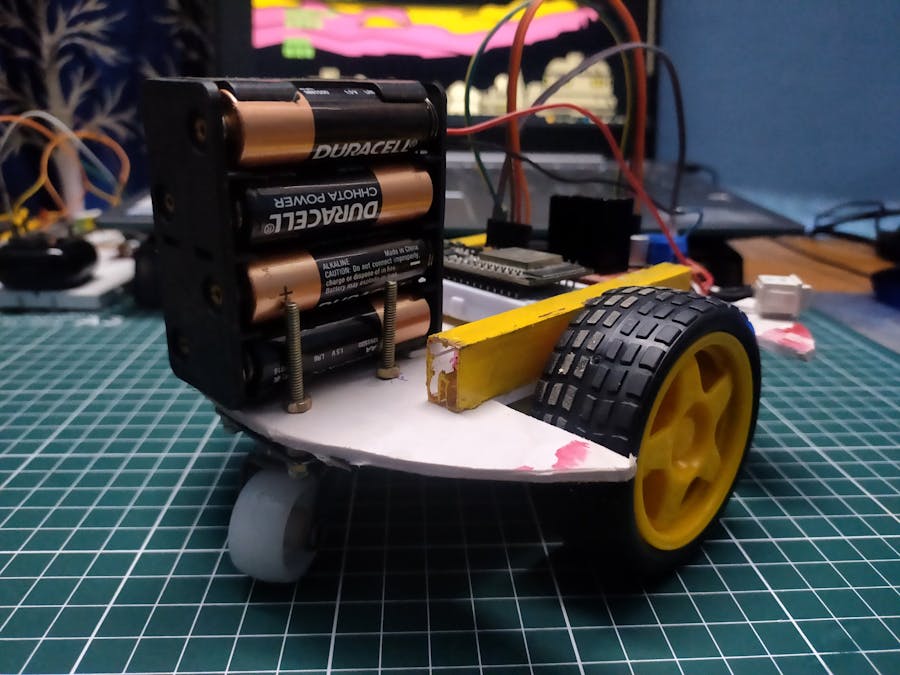
Make sure to have a Chassis for yourself. I used an Acrylic Board and cut out parts for the Wheels to fit.
As you can see, the Bot takes good shape on a chassis like this.
Next, let us connect ESP32 with the Car. We will use ADC pins of the ESP32 for this. Connections will look as follows.
IN1 - GPIO13 | IN2 - GPIO12 | IN3 - GPIO27 | IN4 - GPIO14
Post this connection, your Hardware is Good to Go!
Take reference from the below image on How the bot should roughly Look like.
Let me first explain the point of Local Server Mode over here.
In this case, the ESP32 will be a server whose Access Point is the WiFi, the ESP32 is connected with.
So, to access the ESP32's IP address, I can connect with the same Access Point, i.e. the WiFi. Now, when I enter the ESP32's IP address in the URL body, I'll be able to access the ESP32 indirectly. This is similar to a Mesh Network.
This broadens the network connectivity for a server that is present locally.
The other way around is by creating an Access Point on the ESP32 itself. But for that, the device we will use to control the ESP32 needs to be connected to it directly. Similar to a Star Network.
Basically, in the first way ESP32 is connected to the Home WiFi hotspot and using it as a HUB to make interconnectivity broader. In a second way, ESP32 is creating a WiFi hotspot so we need to connect to the ESP32 to control it.
CLOUD SERVERIn this case, we are open to using any IoT Service to control over the Internet. We can use REST API, Websocket, MQTT, etc for communication purposes. But one main concern over here is the necessity of access of ESP32 to the Internet.
We will use an already existing service i.e. Blynk IoT. They have existing REST API services that let us use it with any WiFi devices such as ESP32 for prototype purposes and control and monitor the device over the Internet.
The concern should be, that the ESP32 should be connected to any WiFi service that has access to theInternet. Which will lead to easy building and implementing the project.
Woah! That was a lot! Let us now begin with the Main part, i.e. the CODE now.
CODE (LOCAL - MESH)Libraries Used -
#include <WiFi.h>
#include <WebServer.h>
1.WiFi - This library lets the board connect to the internet, using wifi service. more details2. WebServer - This library creates a server on the ESP32 so that the server can wait for the client to access its endpoints. Supports in creating a webserver and running an independent simple webserver. more details
int LeftA=13;
int LeftB=12;
int RightA=27;
int RightB=14;

const char* ssid = " ";
const char* password = " ";

WebServer server(80);
1. Pin Numbers are associated as follows LeftA - IN1.... RightB - IN4. Connected with the GPIO13, 12, 27, 14.
2. Enter the WiFi (any hotspot or Home WiFi)'s SSID and PASSWORD.
3. The 3rd line will create the server on port 80.
while (WiFi.status() != WL_CONNECTED) {
delay(1000);
Serial.print(".");
}
Serial.println("");
Serial.println("WiFi connected..!");
Serial.print("Got IP: ");
Serial.println(WiFi.localIP());
The while loop will remain inside till the status of the connection does not get connected.
And once connected, it will print the IP address of the ESP32 on the Serial Monitor. The IP Address of the ESP32 when we will use it to control the Car.
server.on("/asasasasa", handle_OnConnect);
server.on("/asasasasa/left", left);
server.on("/asasasasa/right", right);
server.on("/asasasasa/forward", forward);
server.on("/asasasasa/backward", backward);
server.on("/asasasasa/stop", halt);
server.onNotFound(handle_NotFound);

server.begin();
Serial.println("HTTP server started");
These are the Endpoints that will help us in controlling the ESP32 from the URL. Basically, we are making a REST server locally that does not require internet.
server.on() function has 2 parameters, first part is the endpoint waiting from the clientside. and 2nd part is a function that gets executed upon the endpoint being triggered. The function is defined in the same code file.
server.begin() function starts the server with the provided details.
void loop() {
server.handleClient();
}
This server handles the server that has been started and controls all the endpoint functions when receiving a request.
void left() {
digitalWrite(LeftA,LOW);
digitalWrite(LeftB,HIGH);
digitalWrite(RightA,HIGH);
digitalWrite(RightB,LOW);
server.send(200, "text/html", SendHTML());
}
This is a sample of the left() funciton that is called in server.on("/asasasasa/left", left);
In this function, the digitalWrite function executes the LEFT TURN on the Car. And then executes a SendHTML() page which was covered in the WebServer Project in my profile.
You can use analogWrite with controlled speed for the motors since we are already using ADC pins of the ESP32.
Now, in case the IP address is 192.168.26.44(visible in the serial monitor), then you can us the below URL in the browser and run it to check and execute the endpoints -
Here, asasasasa works like a Secret Key, without which no one will be able to control the Car.
CODE (LOCAL - STAR)In this case, the ESP32 is creating a WiFi Hotspot which requires an SSID and PASSWORD.
const char* ssid = "ESP32-WIFI";
const char* password = "PASSWORD123";
Here is the SSID and PASSWORD that you can CREATE a Hotspot with, for the ESP32 device.
IPAddress local_ip(192,168,1,1);
IPAddress gateway(192,168,1,1);
IPAddress subnet(255,255,255,0);
The above function will set the IP Address of the ESP32 that is run on the ESP32 Server. You need to access the ESP32 endpoints with the local_ip.
WiFi.mode(WIFI_AP);
WiFi.softAPConfig(local_ip, gateway, subnet);
WiFi.softAP(ssid, password);
Now let us start the ESP32 Server and make the device itself as the Access Point.
You can control the ESP32 Device Access Point from any Computer/Mobile/Device by connecting to its WiFi Hotspot.
That's it so far. Rest all are the same for the Star Network or the Mesh Network.
CODE (CLOUD - BLYNK 1.0)In this method, we will be using the Blynk App (Legacy) and its buttons. Which is the predecessor version of Blynk 2.0. So, there are many changes in this old version.
But because of the App and extra allowance for more functional widgets. We will be using 5 buttons that will control the virtual pins, and the virtual pins will be SET in the ESP32 code as well. Hence executing Forward, backward direction custom functions.
This is a sample layout of the remote with the V0, V1, V2, V3, V4 as the virtual pins. We will refer to the same virtual functions to execute the directions as mentioned earlier.
Library Required -
#include <BlynkSimpleEsp32.h>BlynkSimpleEsp32 - Use the Blynk IoT platform with this library to build IoT applications over simple code. download link
char auth[] = " ";
char ssid[] = " ";
char pass[] = " ";
Here, the auth variable contains the auth token of the Blynk App (account). SSID and PASSWORD of the WiFi connection the ESP32 will connect with which MUST have the Intenet Connection.
Blynk.begin(auth, ssid, pass);This function arranges all the required libraries, headers ports required to be directly used from the App/REST API. And starts the service from this single function.
BLYNK_WRITE(V0)
{
    forward();
    Serial.print("Forward");
}
The above Virtual Pin function is a sample of the functions that get executed on the buttons being pressed or the REST API call being made.
Rest for the directional functions with the motor, and setting up of its variables, all others are the same. (Complete code in Code Section)
CODE (CLOUD - BLYNK 2.0)In this method, we will be using the Blynk 2.0 Cloud and Blynk IoT App and its buttons. Which is the predecessor version of Blynk 2.0. So, there are many changes in this old version.
We first need to Setup on Blynk's Web Dashboard Cloud and then move to the App.
From the Cloud, we get the above Template ID, Device Name and Auth Token.
Next go to Templates > Create new Template > Edit > Create New DataStream > Virtual Pin > Data Type - Integer
We then need to CREATE DataStream, so that we can use the stream for sharing across our data (Virtual pins V0 to V4)
This is a sample layout of the remote with the V0, V1, V2, V3, V4 as the virtual pins. We will refer to the same virtual functions to execute the directions as mentioned earlier.
WebRemote (LOCAL SERVER)This is an essential component of this Project, as it has the capability of working like a remote for the Car that we will control.
The concept is of a basic webpage that has direction buttons. Each buttons have specific URLs it can fetch/execute. We have connected all the endpoints with these buttons.
The endpoints were already defined in the Arduino Code for the ESP32. So whenever a specific endpoint on the IP Address is executed, then the function in the ESP32 is triggered.
Open the HTML script in the code section.
For example, when the following URL is executed -
192.168.26.44/asasasasa/forward
Then, the bot goes forward.
Using the above Remote with same UI (Different HTML file from Code Section) -
But the JS behind will have a different URL. Here, we will be using the Blynk Cloud API URLs for this.
For Blynk 1.0 - http://blynk-cloud.com/auth_token/update/pin?v0=1&v1=1&v2=1&v3=1&v4=1
For Blynk 2.0 - https://blynk.cloud/external/api/batch/update?token=<auth_token>&v0=1&v1=1&v2=1&v3=1&v4=1
If button is pressed, then send value 1, when some other button is chosen, all other buttons will go 0. (Hence colour of any other button goes dark ).
Please don't send value 1 for all at once as provided in example.
Add the auth token in the HTML file in the Code Section.
BLYNK_WRITE(V0)
{
    int pinValue = param.asInt();
    if (pinValue == 1){
        forward();
    }
    else{
        continue;
    }
    Serial.println("Forward");
}
The above Virtual Pin function is a sample of the functions that get executed on the buttons being pressed or the REST API call being made.
For more information on REST APIs -
Blynk 1.0 - https://blynkapi.docs.apiary.io/#reference/0/write-pin-value-via-get/write-pin-value-via-get
Blynk 2.0 - https://docs.blynk.io/en/blynk.cloud/update-datastream-value
For more information on Hardware Code -
https://examples.blynk.cc/?board=ESP32&shield=ESP32%20WiFi
This was ALL. A simple Arduino Code and an HTML script.
Make sure to open the HTML page from file server itself. It will not work if you upload it to any hosting platform, since it uses unsecured http connection to a specified IP Address
More on Blynk 2.0 IoT Platform in here -


_3u05Tpwasz.png?auto=compress%2Cformat&w=40&h=40&fit=fillmax&bg=fff&dpr=2)
Comments