

Hardware components | ||||||
 |
| × | 1 | |||
 |
| × | 1 | |||
 |
| × | 1 | |||
Software apps and online services | ||||||
| ||||||
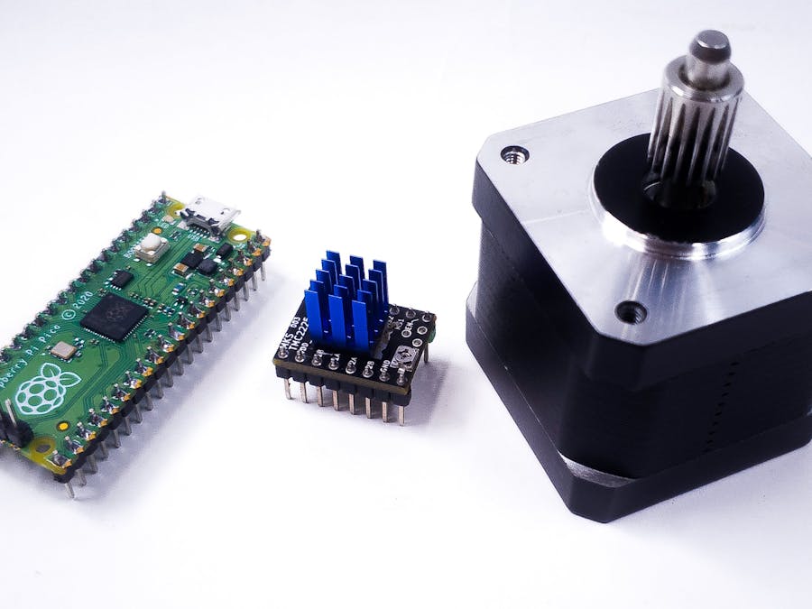
I am currently working on a project that requires me to control stepper motors using stepper drivers like the a4988, tmc2208, and other similar drivers, these drivers use a Step/Dir interface to control thestepper motors, the step signal is kind of like a PWM signal, but instead of controlling power output, you’ll be controlling thenumber of steps taken by the stepper motor; with the frequency of the signal dictating how fast the stepper motor will turn. The direction signal is just high or low depending on the direction you want the stepper to move in.
You can produce these signals with the good old-fashioned bit-banging, where you turn on a pin, delay for a specific time, turn off the pin, and then delay again, this approach works and it’s totally useable for simple projects, but for complex projects, you’ll need a much more efficient control scheme, which is where the raspberry pi Pico’s PIO interface comes in.
The raspberry pi Pico, has 2 programmable io’s (PIO), each offering 4 state machines. These 8-state machines can accurately control stepper drivers without blocking or stalling your main code loop.
I won’t be going into details about how the PIO works, mainly because my knowledge on the topic is limited, and there is already a lot of great content on pi pico’s PIO, I’ll leave links to some of them below. I will mainly focus on implementing the PIO as a step/ direction stepper motor driver. So, if you are looking for some general information, or if you're looking for a solution that already works, you are in the right place.
The first thing to know about Step/Dir control is; that it only requires one integer value, this value depends on two factors, one is the resolution of the stepper motor, and the second is the micro stepping settings on whichever stepper driver you’re using.
As an example. If I want to move 90 degrees on a 1.8-degree stepper motor, using a ¼ micro-stepping driver, the integer value required will be (4*90)/1.8, which is equal to 200, by replacing 90 with different angles, you get the required integer or step pulse count.
Our goal is to tell the RP2040’s PIO to generatepulses with a count equal to this integer value.
The RP2040 chip on the raspberry pi pico runs pretty fast at 133Mhz which results in a clock cycle of 7.52 nanoseconds, that’s way too fast for a stepper driver, so we need to run the PIO on the chip at a lower speed, most stepper drivers will work reliably with pulse delays down to 200 microseconds, but for this demonstration, I’ll be using 500 microseconds as the minimum delay.
Timing GotchasBecause the pi Pico is so fast and we’re running the PIO so slow, there are some timing requirements to keep in mind.
Data rate:
The output shift registers for the state machines on the RP2040 can only hold 32 bits at a time, so if we use the 90-degree example above, we will need to send the pulses 32bits at a time, so for 200 steps, we’ll need to send 32 + 32 + 32 + 32 + 32 + 32 + 8 within different and not necessarily sequential loops in the main program, we do that by checking if the Tx fifo is empty before sending the next 32 bits, this does not block the main loop as we only need to run a few lines of code to check and send the next bits.
Changing direction:
To change directions in a Step/ Dir interface, you simply flip the state of the direction pin, because we are changing this state in the main program loop which is much faster, we need to pay attention to when a direction change can be done. Say we sent out the first 32 bits of the 90-degree example, the state machine will take 32ms (32*2*500us) to process those bits, in that time, the main loop will run 4256000 times (assuming a 1 cycle loop), so it’s very likely that we calculate a new step integer in the opposite direction within that time, in that case, we’ll have to wait for the state machine to send out all its register data before issuing the direction change and then sending the newly calculated integer steps. With some smart programming, this can also be done in a way that does not block the main program.
CodeTo facilitate multiple stepper control, I’ve written the stepper motor parameters into a struct, this way we can have multiple structures representing multiple stepper drivers with their associated pin assignments and PIO state machine index.
struct STEPPER_DRV
{
    int StepsToTake = 0;
    bool activedir = true;
    bool dirchange = true;
    float ActiveAngle = 0.0; // 360/res
    int DIR_PIN = 0;
    int STEP_PIN = 0;
    int HOME_PIN = 0;
    int FULLSTEP = 800;
    int directionchangeDelayCounter = 0;
    PIO stm_pio = pio0;
    int stm_sm;
};

struct STEPPER_DRV stepperMotor1;
In the code above, I define the standard struct named “STEPPER_DRV“ with all the required parameters for a standard stepper driver, I then created a new stepper instance called “stepperMotor1“.
Note that FULLSTEP is the number of steps that makes a full revolution. in this example, the stepper motor is a 200-step motor and the driver is configured for 1/4 microstepping, resulting in a FULLSTEP value of 800.
void setupGPIO()
{
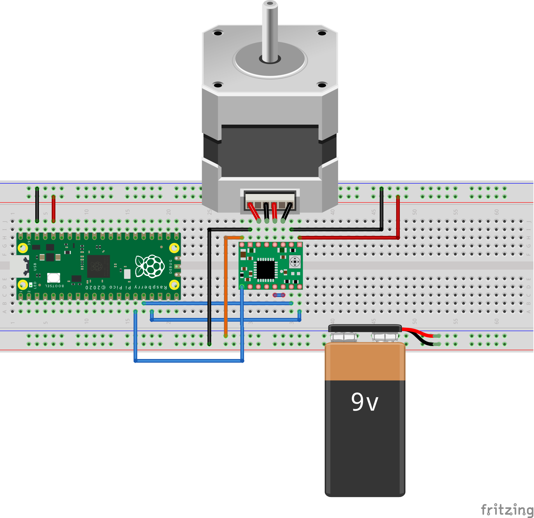
stepperMotor1.DIR_PIN = 17;
stepperMotor1.stm_sm = 1;
stepperMotor1.STEP_PIN = 16;
stepperMotor1.FULLSTEP = 800;
// stepper enable pin
gpio_init(STM_EN);
gpio_set_dir(STM_EN, GPIO_OUT);
// gpio_put(STM_EN, 0);
// stepperMotor1 dir pin
gpio_init(stepperMotor1.DIR_PIN);
gpio_set_dir(stepperMotor1.DIR_PIN, GPIO_OUT);
// gpio_put(stepperMotor1.DIR_PIN, 1);
// inbuilt led
gpio_init(LED_PIN);
gpio_set_dir(LED_PIN, GPIO_OUT);
}The above snippet is where I configure the parameters for the stepper driver, I set the step pin used by the pio state machine to 16, and the direction pin to 17, stepper enable pin is also set to 15 on an earlier line in the full code. stm_sm defines the state machine number to use, this can be any number between 0 - 3.
Configuring the State Machine:
The main configuration to watch out for is the state machine’s running frequency, I set it to 10000Hz; setting it lower will make the stepper turn slower, and setting it higher will make the stepper turn faster.
void setupPIO()
{
    // stepper 1 pio
    uint stm_offset = pio_add_program(stepperMotor1.stm_pio, &stepper_1_program);
    stepper_1_program_init(stepperMotor1.stm_pio, stepperMotor1.stm_sm, stm_offset, stepperMotor1.STEP_PIN, 10000, true);
}
The full stepper.pio configuration code can be referenced in the full code on GitHub.
How the State Machine Sends out Step Signals
.wrap_target
bitloop:
    out x, 1
    jmp !x do_zero ; Branch on the bit we shifted out
do_one:
    set pins 1     [STD + 3]
    set pins 0     [STD]
    jmp  bitloop
do_zero:
    set pins 0   ; Or drive low
.wrap
The above assembly code is the loop that runs in the state machine, the first line out x, 1 shift one bit out of the Output Shift Register(OSR) into the scratch register x one bit at a time, and the second line checks if the bit shifted is a one or a zero, if its a one the code continues to do_one, where the step pin is set high for STD+3 clock cycles, and then set low for STD cycles before returning to jmp marker bitloop. If the shifted bit is a zero, the code continues to do_zero where the step pin is simply set to zero for STD clock cycles before looping back to the beginning. STD is a delay value set to 1 earlier in the code, this value can be used to adjust the speed of the stepper motor, much like the frequency, its value can be set anywhere from 1 - 28.
Main Loop
int main()
{
    stdio_init_all();
    setupGPIO();
    setupPIO();
    int changeDegreeCounter = 0;

    float degPos[7] = {45, 315, 225, 90, 180, 135, 0.5};
    int activedegindex = 0;
    while (true)
    {
        if ((time_us_64() / 1000) - changeDegreeCounter > 2000 && activedegindex < 7)
        {
            activedegindex += 1;
            changeDegreeCounter = time_us_64() / 1000;
        }
        getStepperSteps(&stepperMotor1, degPos[activedegindex], 0);
        moveSTEPPER_DRV(&stepperMotor1);
        readtobuffer();
        processinData();
    }
}
There is simultaneously a lot and a little going on with the main loop, so I’ll just summarize: the first three lines are calls to the setup functions in the code, and the next three lines are variables used to initially move the stepper motor to all the angles defined in the degPos array. When the pi pico powers up, it will move the stepper to all the positions defined in this array.
The main functions in the loop are getStepperSteps and moveSTEPPER_DRV; getStepperSteps takes three parameters: the reference to the stepper driver instance (&stepperMotor1), a float angle from 0.01 - 360 for the position to move the stepper to and an integer indicating what path to take, in the sample code I’ve set the path variable to 0 which tells the function to calculate the shortest path to the position, it can also be set to 1, which means always move forward, or 2 which means always move backward.
Whenever the getStepperSteps function is called, the step integer value is calculated and stored in the StepsToTake variable inside stepperMotor1 struct, so that when the second function moveSTEPPER_DRV is called, the step integer is converted into 32bit chunks and sent to the state machine’s tx fifo where it’s then forwarded to the stepper driver.
To test the stepper motor positioning, I implemented serial terminal control, so by connecting to the pi pico through a terminal app like putty, we can issue specific position commands to the pi pico, which is what the functions readtobuffer and processinData do.
For the full PIO Stepper driver code head to my GitHub repository.
Gary Explains - https://www.youtube.com/watch?v=QlKtEA5XKc4&t=1409s
Life With David - https://youtu.be/YafifJLNr6I


_3u05Tpwasz.png?auto=compress%2Cformat&w=40&h=40&fit=fillmax&bg=fff&dpr=2)
Comments