

Hardware components | ||||||
 |
| × | 1 | |||
| × | 1 | ||||
 |
| × | 1 | |||
 |
| × | 1 | |||
Software apps and online services | ||||||
| ||||||
 |
| |||||
| ||||||
 |
| |||||
Hand tools and fabrication machines | ||||||
 |
| |||||
- Introduction
This network sensor is based on Ethernet networks and operates with IEEE 802.3 specifications. Ethernet protocols are considered data-link layer protocols.
- System Design
1. PIC16F88: It is a Microcontroller has several features. The main features that we will get benefit from them here are: bank of digital i/o pins in addition to the Analog-to-Digital Converter (ADC) channels.
2. ENC28J60: This controller is used here, because the PIC16F88 alone doesn’t support Ethernet, which means the PIC doesn’t has the possibility to access the network. The ENC28J60 is a stand-alone Ethernet controller with an industry standard of Serial Peripheral Interface (SPI). It is designed to serve as an Ethernet network interface for any controller equipped with SPI. In fact, it meets all of the IEEE 802.3 specifications.
Furthermore, the ENC28J60 has its own C library (EthEnc28j60.c). This library is designed to simplify handling of the underlying hardware. SPI Ethernet ENC28J60 Library supports the following functions :
IPv4 protocol.
ARP requests.
ICMP echo requests.
UDP requests.
TCP requests (no stack, no packet reconstruction).
ARP client with cache.
DNS client.
UDP client.
DHCP client.
packet fragmentation is NOT supported.
3. 74HCT245: This IC acts as an octal transceiver featuring non-inverting 3-state bus compatible outputs. Compatible outputs in both send and receive directions.
The system design is accomplished by Protous ISIS 7. It is used to make the hardware connections and to modify the connection as it is required, then to test the work and performance of each of the hardware connections and the flow of the program inside the PIC. Figure 1 shows the hardware connections of the Ethernet Network Sensor.
- Work principle of this Ethernet network sensor
A program has been written inside the PIC16F887 (Programmable Interface Chip) by use of mikroC compiler. This program is written by use of C programming language. Where this program is specifying the functionality of the network sensor as follow :
1. Specifies the ENC28J60 start transmitting buffer and end of transmitting buffer.
2. Constructs the header of each protocol we used in network connection.
3. Configures the required control registers of the ENC28J60.
4. Reads an input signal, and makes the desired output value according to the measured input signal.
The program is as follow:
//Engineer : Ahmed M. Alfadhel

#include "__EthEnc28j60.h"
// duplex config flags
#define Spi_Ethernet_HALFDUPLEX 0x00 // half duplex
#define Spi_Ethernet_FULLDUPLEX 0x01 // full duplex

//ehternet NIC pinout
sfr sbit SPI_Ethernet_Rst at RC0_bit;
sfr sbit SPI_Ethernet_CS at RC1_bit;
sfr sbit SPI_Ethernet_Rst_Direction at TRISC0_bit;
sfr sbit SPI_Ethernet_CS_Direction at TRISC1_bit;
// end ethernet NIC definitions

/*************** Data link layer protocol ,DIX Ethernet header  *************/
unsigned char myMacAddr[6] = {0x1c, 0x65, 0x9d, 0x2b, 0xe2, 0x7f} ; // my MAC address
unsigned char desMacAddr[6] = {0xff, 0xff, 0xff, 0xff, 0xff, 0xff} ;
unsigned char pack2[2]={0x08,0x00} ; //Protocol type , Data LENGTH

/************** network layer Protocol ,IPv4 header ***********************/
unsigned char ipv4IHL=0b01000101;
char service_type=0;
unsigned int total_length[2]={0,35};
unsigned int id[2]={0x00,0x01};
unsigned char flag_offset[2]={0b01000000,0b00000000};
unsigned int TTL=100;
unsigned char protocol=17;
unsigned char checksum[2]={0x91,0x61};
unsigned char myIpAddr[4]={192,168,137,60};
unsigned char dest_ip[4]={192,168,137,255};

/************ tranport layer , UDP header **********************/
unsigned char SourcePortNumber[2]= {0xce,0x80}; //52864
unsigned char DestPortNumber[2]= {0x1f,0x90}; //8080
unsigned char length[2]={0,24}; //since minmum UDP header length is 8 bytes + 16 Bytes length of data
unsigned char check2[2]= {0x00,0x00}; //none .

/************* the program & functions *************************/
unsigned int light_res,ad1,ad2;
void main()
{
ANSEL = 0x04; // Configure AN2 pin as analog
ANSELH = 0; // Configure other AN pins as digital I/O
C1ON_bit = 0; // Disable comparators
C2ON_bit = 0;
ADC_Init(); // Initialize ADC module with default settings
SPI1_Init();
TRISA = 0xff ; // set PORTA as input for ADC
TRISD = 0 ; // set PORTD as output
portd=0;
TRISE = 0; // set PORTE as output
delay_ms(10000); // wait until ENC28J60 work
SPI_Ethernet_Init(myMacAddr, myIpAddr,Spi_Ethernet_FULLDUPLEX) ;

spi_ethernet_putbyte(0x0f); //setting bytes

//Putting Header of data link layer
SPI_Ethernet_putBytes(desMacAddr,sizeof(desMacAddr));
SPI_Ethernet_putBytes(myMacAddr,sizeof(myMacAddr));
SPI_Ethernet_putBytes(pack2,sizeof(pack2));

//Putting header of network layer IPV4
SPI_Ethernet_putByte(ipv4IHL);
SPI_Ethernet_putByte(service_type);
//SPI_Ethernet_putBytes(total_length,sizeof(total_length));
SPI_Ethernet_putBytes(id,sizeof(id));
SPI_Ethernet_putBytes(flag_offset,sizeof(flag_offset));
SPI_Ethernet_putByte(TTL);
SPI_Ethernet_putByte(protocol);
SPI_Ethernet_putBytes(checksum,sizeof(checksum));
SPI_Ethernet_putBytes(myIpAddr,sizeof(myIpAddr));
SPI_Ethernet_putBytes(dest_ip,sizeof(dest_ip));

//Putting Header of Transport Layer , UDP header
SPI_Ethernet_putBytes(SourcePortNumber,sizeof(SourcePortNumber));
SPI_Ethernet_putBytes(DestPortNumber,sizeof(DestPortNumber));
SPI_Ethernet_putBytes(length,sizeof(length));
SPI_Ethernet_putBytes(check2,sizeof(check2));

spi_ethernet_putstring("NETWORK SENSOR");

while(1) // do forever
{
light_res=ADC_Read(2); // Get 10-bit results of AD conversion
ad1=light_res;
ad2=light_res>>8;
SPI_Ethernet_CS=0;
spi1_write(0b01000010); // writing to ETWRPL
spi1_write(0x39);
Spi_ethernet_cs=1;
SPI_Ethernet_CS=0;
spi1_write(0b01000011); // writing to ETWRPH
spi1_write(0);
Spi_ethernet_cs=1;
SPI_Ethernet_putByte(ad2);
SPI_Ethernet_putByte(ad1);
SPI_Ethernet_CS=0;
spi1_write(0b01000100) ; // writing to etxstl
spi1_write(00 );
SPI_Ethernet_CS=1;
SPI_Ethernet_CS=0;
spi1_write(0b01000101) ; // etxsth
spi1_write(00 );
SPI_Ethernet_CS=1;
SPI_Ethernet_CS=0;
spi1_write(0b01000110) ; // etxndl
spi1_write(0xff);
SPI_Ethernet_CS=1;
SPI_Ethernet_CS=0;
spi1_write(0b01000111) ; // etxndh
spi1_write(00);
SPI_Ethernet_CS=1;
SPI_Ethernet_CS=0;
spi1_write(0b01011100); // eir
spi1_write(0b0000000);
SPI_Ethernet_CS=1;
SPI_Ethernet_CS=0;
spi1_write(0b01011011); // eie
spi1_write(0b00001000) ;
SPI_Ethernet_CS=1;
SPI_Ethernet_CS=0;
spi1_write(0b01011111); // econ1
spi1_write(0b00001000);
SPI_Ethernet_CS=1;
SPI_Ethernet_CS=0;
spi1_write(0b01011110); // econ2
spi1_write(0b10000000);
SPI_Ethernet_CS=1;
SPI_Ethernet_CS=0;
spi1_write(0b01000111); // ebstcon
spi1_write(0b10000000);
SPI_Ethernet_CS=1;

// Checking The Sensing Process
if(light_res<0b1110110110) // =950 , physical value 4.75v
portd=0x01;                // Led : ON
else
portd=0x00;                // Led : OFF
Delay_ms(500);
}
}
According to above program, the sensor will work as follow:
1. The network sensor will sense an input (Temperature, light, sound, action,... ). In this project a photo-resistor is used to sense the ambient light.
2. The input will be measured as analog signal. Then converted to digital signal.
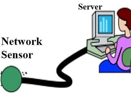
3. The digital signal is transmitted as packets by the network sensor to the end station device such as central server computer to collect the data.
4. The central server will tab (pick up) the packets by use the interface application program.
5. The network sensor can do some actions according to the measured analog signal, like (Operating a device). In this project if the ambient is dark the sensor will operates a LED, otherwise the LED is OFF.
- Collecting the data from thesensor by the server
After the project is built in Protous and loaded the program in the PIC, now it is able to send packets by the virtual network sensor ( by Protous), and these packets were will be recorded by Wireshrak at the another computer(server). As shown in Fig. 2 below:
The high-lighted value (03 f9) in Fig.2 above is 2 bytes hexadecimal number refers to the current voltage value of the photo resistance, in Decimal 1017 where the full scale reading is (03 ff) h and corresponds to 1023, and as a physical value is 5 Volts.
To make Protous program able to make simulation over the network it is needed to install Winpcap driver (network driver) from the internet. Then you should follows this procedure :
In the window of project in Protous program, R.click the ENC28J60 and
choose Edit properties from the list.
From window of “Edit properties” window specify the network card
number that the current computer work with.
After that the Ethernet network sensor has been built as a device and succeeded to transmit packets to the server then recording the received packets by Wireshark. Figure 3 below shows the construction of this sensor using bread board.
- Interface Program
Since this network sensor has been programmed to communicate via UDP packets, a computer application program has been made to receive the UDP packets only from the network sensor and read the contents of each UDP packets.
This application program has been made by use Microsoft Visual Studio 2010 by C#. And the code for this program is attached in the end of this page.
Figure 4 below shows the GUI for this application program.
This application is tested between two computers, where is worked successfully. But when the program is running for the network sensor, it doesn’t view any packet. It seems that I need to add a definition of an Application Layer Protocol in order to make this Application (Interface Application) pick up the packets come from the network sensor.
- Power on the network sensor
In order to power on the network sensor, follow the following steps :
Set the TCP/IP settings of your computer (server) as follow :
IP address :192.168.137.X
Subnet mask: 255.255.255.0
Connect the Network sensor to your pc through UTP cable (straight or cross ).
Power on the network sensor by connect the power cable (AC 220v).
Wait to 10 seconds for initialization the device.
Then you will note it began sensing the medium.
Note : This network sensor is programmed with the IP 192.168.137.60


Comments